This thread has been locked.

If you have a related question, please click the "Ask a related question" button in the top right corner. The newly created question will be automatically linked to this question.

LM25118EVAL: About oscillation of output voltage

Part Number: LM25118EVAL
Other Parts Discussed in Thread: LM25118

Hello.
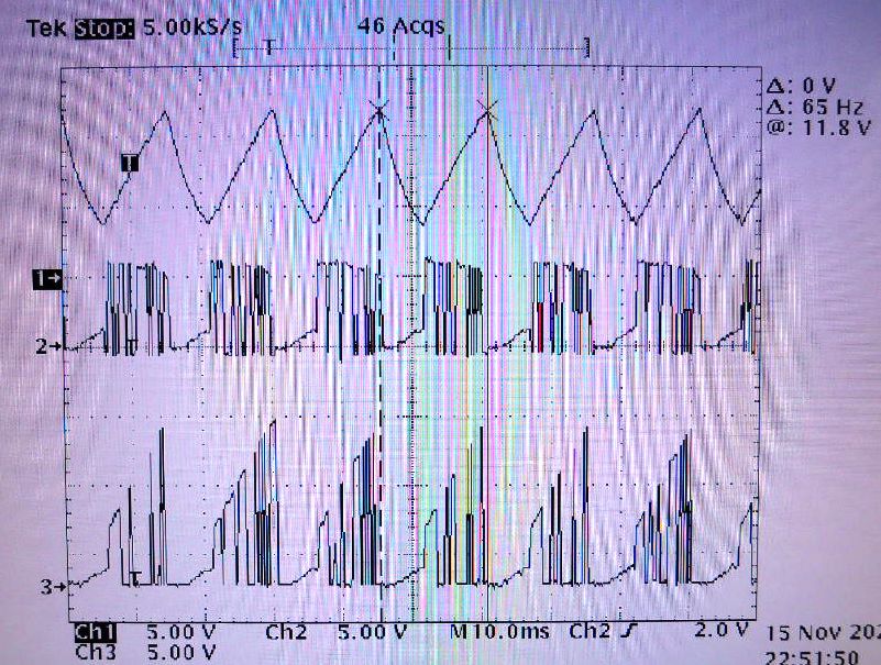
Input voltage (6V) was applied after connecting load resistance 12Ω using LM25118EVAL.
The output voltage oscillates and does not operate normally.

I use it with the load connected.
Please tell me the cause of oscillation and the countermeasures.
The circuit constant of EVAL remains the original.

Please.

  • Hi User,

    Thank  you for considering the LM25118. The EVB was passed factory test at full power, so it should work. And, this is not a new design. The EVB has been on released for almost 10 years, and many have been shipped.  This is the first time I have ever heard about such issue. 

    Could you use a scope to monitor the input voltage?  The multi meters cannot tell whether or not the input is stable.  Make sure your input source is solid stable, at the EVB input port.  I do see thin and long wires for your input connection, thinner than the multi meter probe wires.  

    To better help us understand the issue, please monitor the following:

    (1) Vin, Vout, SW1 and SW2, on the same scope picture.  Please show both zoomed in (a couple of switching cycles) and zoomed out (many cycles).

    Thanks,

    Youhao Xi, Applications Engineering

  • Thank you for your prompt contact.
    I couldn't send the attached waveform TIF file
    I will send you an image
    Ch1 = Vout Ch2 = SW1 Ch3 = SW2.
    The current capacity of the input power supply used is 2.5A.
    According to the answer given, the current capacity of the input power supply used is small.
    I understood that the output fluctuated.
    At a later date, we will measure using a large-capacity power supply.
    thank you very much.

  • Hello.
    Measurement was performed using an input power supply with a current capacity of 5A.
    Shows the waveform.

    ch1 = input voltage ch2 = output voltage ch3 = SW1 ch4 = SW2

    Normal operation has been confirmed.

    thank you very much.
  • Thank you very much for the updating.  I am glad that you solved the problem.  Good luck in your project.

    Thanks,

    Youhao