This thread has been locked.

If you have a related question, please click the "Ask a related question" button in the top right corner. The newly created question will be automatically linked to this question.

TPS23861: TPS23861 no output

Part Number: TPS23861
Other Parts Discussed in Thread: TIDA-00465, TPS7A4001

Dear all:

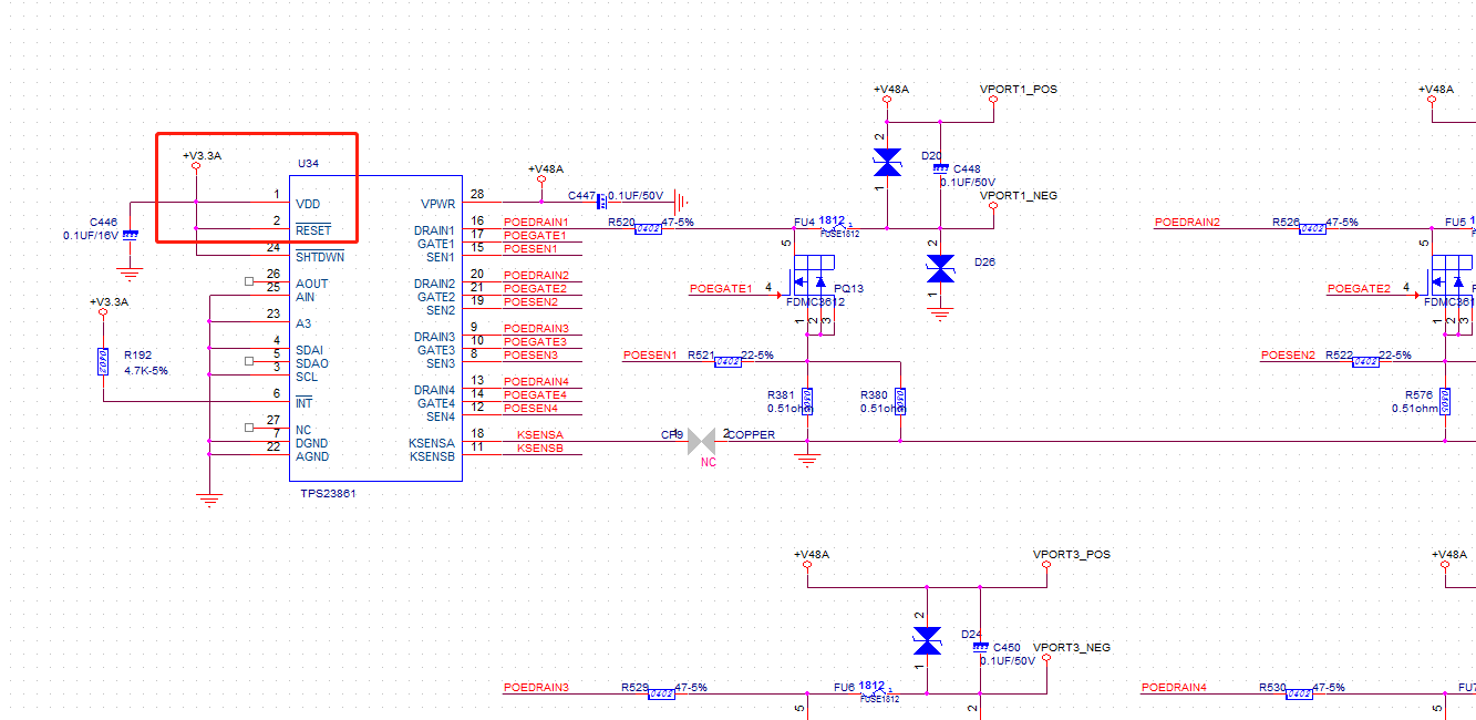
The motherboard was normal at first, and it took a while to find the POE interface was abnormal.TPS23861 no output.

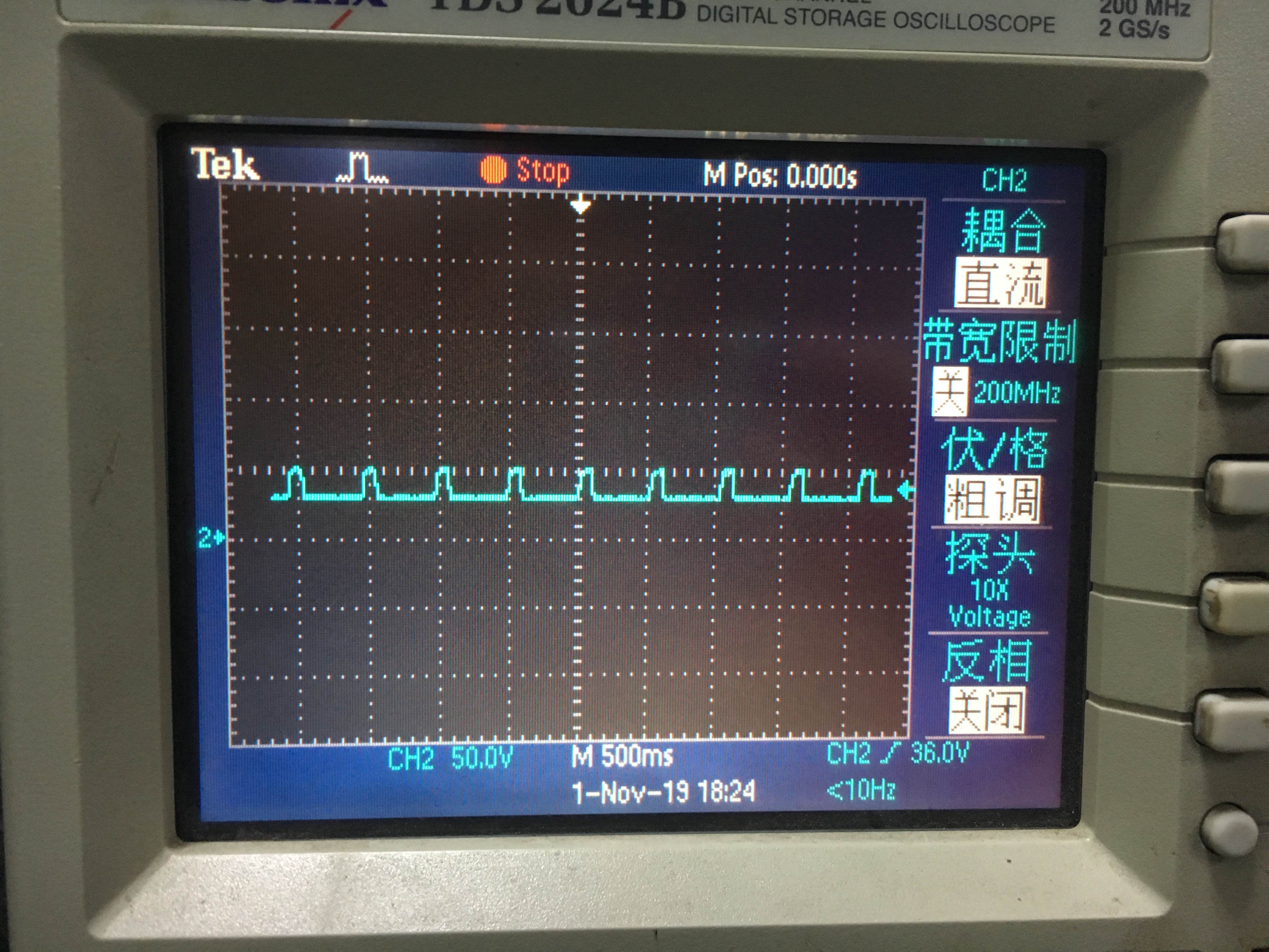
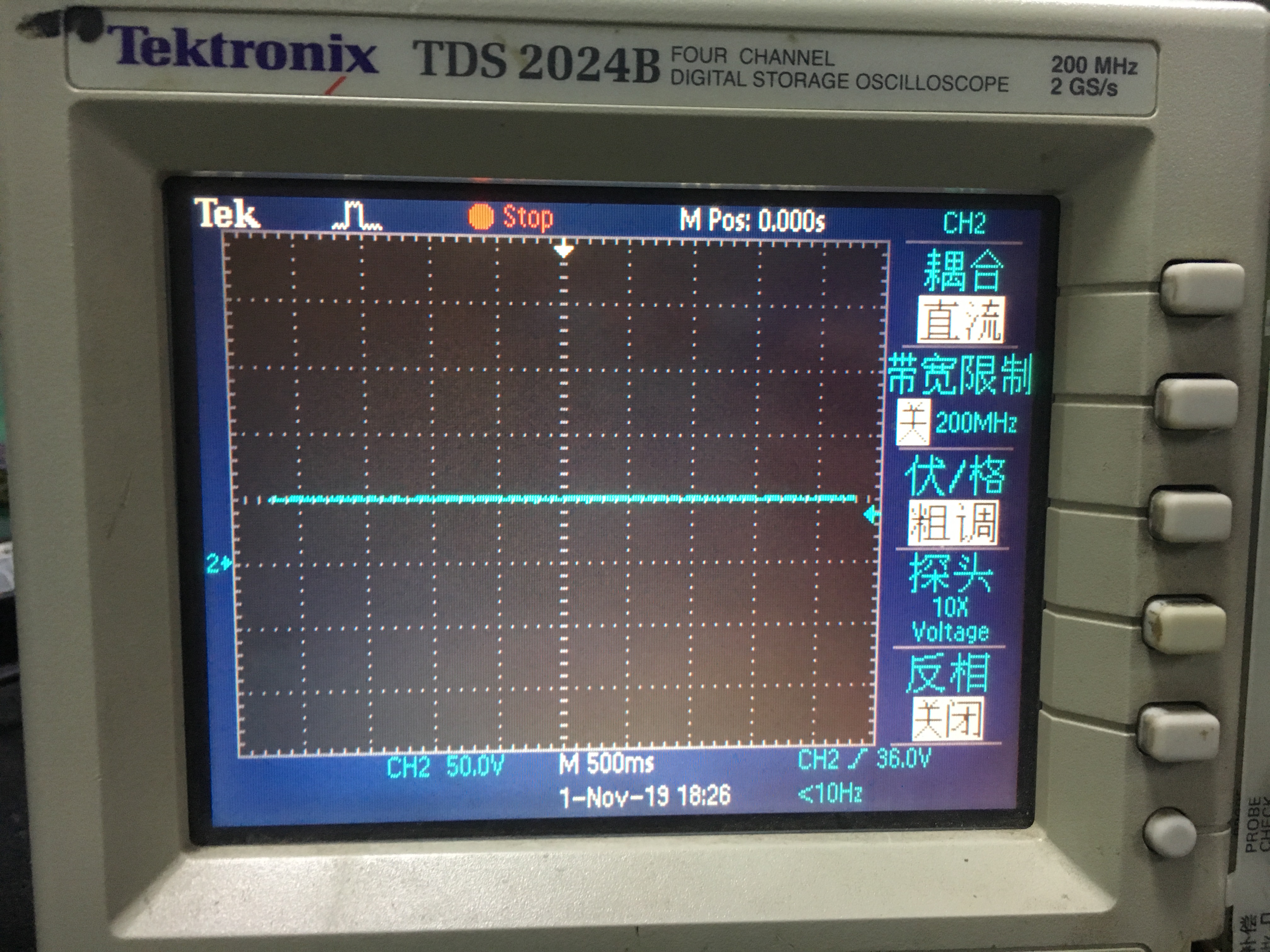
Use the voltmeter to touch the positive and negative poles of the power supply pin of the PSE device respectively. The voltage is displayed as 0 volts.It seems that there should be no detection.

Originally thought to be a single board problem, now I found more than one.

Now I want to know what went wrong with the chip and what is the cause of the problem.

Thank!

  • Connected to the POE device without powering out

  • Hi Shiheng,

    Can you explain more about your test setup and test condition?

    1. What was connected to the PSE port when this problem happened?
    2. Can you take some waveform of the port current and port voltage at the time when port shut down?
    3. If the IC recoverable after power cycle? or the IC is completely dead?
    4. Please send me the schematic of the DCDC(48 to 3.3V for PSE VDD).
    5. If possible, please connect I2C lines to USB-TO-GPIO and use PI commander GUI to read the event register status.

    Thanks,

    Penny

  • Hi Penny,

    As follows:

    1.POE camera.

    2.Is the port shut down when the PD device is disconnected or the power is turned off?

    3.The IC has power, but it does not work. There is no detection waveform when connected to the PD device.

    4.Sorry, not very understanding, which part of the schematic you need?

    5.Sorry, the IIC signal is not coming out.

    and,Normal board waveform when no PD device is connected

    Waveform of the abnormal board when the PD device is not connected:

  • Hi Shiheng,

    Please see my response inline below:

    Sorry, not very understanding, which part of the schematic you need?

    [Penny] There's must be a circuit to convert the 48V to 3.3V to supply TPS23861's VDD. Can you send me the schematic? TPS23861 requires power on sequence. Please review the app note here: http://www.ti.com/lit/an/slva723/slva723.pdf

    Can you also take a waveform including PSE's Vpwr(48V), PSE's VDD(3.3V) and PSE's RESET pin during start up? I want to check the power on sequence to make sure it is correct. 

    For the abnormal board, did all ports have the same behavior or only some ports malfunctioned? Can you please check the port's MOSFET and see if the MOSFET is damaged or not? Please replace the MOSFET and see if the port gets back to normal.

    Thanks. 

    Penny

  • Hi Penny,

    1.Schematic in the attachment,3.3V.pdf

    2.The waveform is as follows:

    CH1(48V)&CH2(VDD&RESET),VDD and RESET pins are connected together.

    3.For the abnormal board, all ports have the same behavior.I switched the MOSFET of the normal board to the abnormal board, and the abnormal board still has problems. The normal board is no problem.

    I think the chip should be broken. What I want to know now is the cause, because the customer wants to know how it is damaged, and can prevent it in the future.

    Thanks. 

  • Shiheng,

    Please replace the TPS23861 IC to verify if the IC is damaged. Looking at the Vpwr,RESET, VDD waveform, actually the power on sequence is not met. Please read the app note:http://www.ti.com/lit/an/slva723/slva723.pdf and make sure the RESET pin is held low before Vpwr reaches out to its UVLO(28V max). Not meeting the power on sequence could bring the device into unknown state which is not recoverable. Thanks.

    Best regards,

    Penny

  • Penny,

    The following timing is normal, and there is no big difference from the abnormal board.

    The following timing is the abnormal board.

    Is the timing of this motherboard initially incorrect?Could it be that the reason for the damage of these motherboards is that the timing is wrong?

    Some motherboards have no problem, just that it looks like there is no problem. In fact, the problem has not yet been shown. Is my understanding correct?

    Can I explain to the customer that the cause of this problem is that the timing is incorrect?Do you have any other different opinions to tell me?

    Thanks. 

  • Hi Shiheng,

    With improper power on sequence, there's a chance that the device will enter unknown state and couldn't recover. It is not 100% failure rate for the ICs. So, it is high recommended to fix the power on sequence issue. Thanks. 

    Best regards,

    Penny  

  • Hi Penny,

    This circuit diagram is a demo diagram given by TI. There should be no mistakes. The attachment is a demo diagram. Please help us to see if there is a problem.DEMO.pdf

    Thanks. 

  • Hi Shiheng,

    TIDA-00465 uses TPS7A4001 with adjustable UVLO but I didn't find this circuit in your schematic. Thanks. 

    Best regards,

    Penny

  • Hi Penny,

    Thank you for checking the schematic for me.It seems that this circuit does have problems, I will modify the next version of the circuit schematic, thank you!

    At present, the reason for the damage of TPS23861 is that the power-on sequence is not correct. I explain this reason to the customer. If I find other problems with the motherboard, can I ask you again?

    Thanks. 

  • Shiheng,

    Sure. Please click resolved button and create a new thread when you have further questions. Thanks.

    Best regards,

    Penny