This thread has been locked.

If you have a related question, please click the "Ask a related question" button in the top right corner. The newly created question will be automatically linked to this question.

TPS62736: Buck Topology Equations

Part Number: TPS62736

*question is not specific to TPS62736 but on a general document for power management devices*

Hello and good day!

Can you please advise if there is a documentation of how the equations are derived in this guide?
Customer is asking for it and is specifically asking about buck's Q1 FET voltage -- if the Vf sign is positive because of reverse bias?

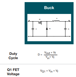
The same question has been raised on the first line of equation on section 3.3.1 of this document

Thank you for your usual support!

  • Hi Elisha,

    The first app notes referred to in the app note below should explain everything:

    Alternatively, if you do a wikipedia search for buck converter, the equations are derived there as well.

    Regards,

    Jeff

  • Elisha,

    The first appnote in the summary appnote above is below. Pages 5 and 6 derive the equation for duty cycle, D, using Vd instead of Vf.  That app note eventually removes the looses across the FET (VDS), the inductor (ILxRL) and VD but if you leave in VD you see that it is correct.

    I frankly do not understand the VQ1 equation.  During Q1 on time, the diode is reverse biased with VIN across it but during the off time, the diode is forward biased.and VQ1=VIN-Vf. 

    Regards,

    Jeff

    www.ti.com/.../slva057.pdf