This thread has been locked.

If you have a related question, please click the "Ask a related question" button in the top right corner. The newly created question will be automatically linked to this question.

LM3407: No output from LED buck switcher circuit

Part Number: LM3407

Hi,

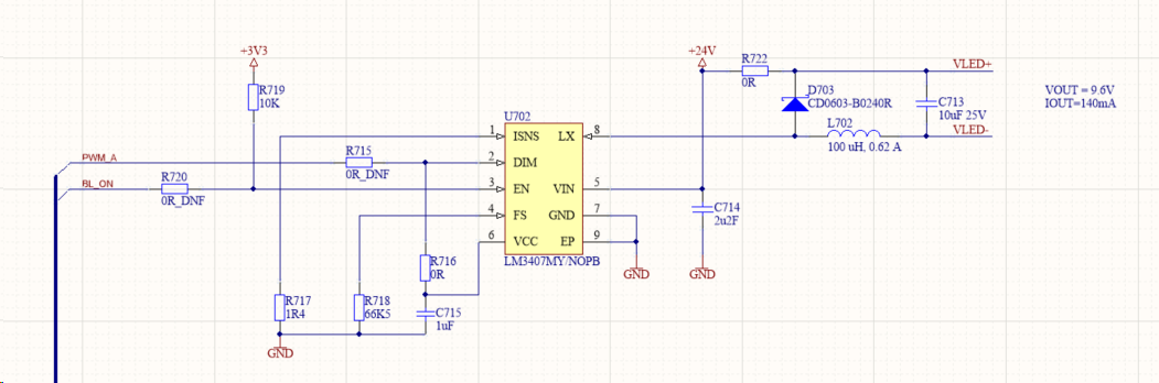
We have the following design developed using Webench, and now implemented in our PCB.  However, it doesn't appear to provide any voltage at all to the LED back light I am using.

Our implmentation matches  the schematic, am I missing somthing obvious?

The LEDs are arranged as 7 parallel rows of 3 series LEDs. 21 in total. IF = 140mA, VF = 9.6V +/- 1.2V

I've attached the outputs from Webench. 

Thanks and regards,

Andywebench_design_LED Power Design.pdf

  • Hello Andy,

    It appears it should work as drawn.  Have you looked at any of the signals when powering up?  Input voltage, output voltage, switch node, enable and DIM?  Have you verified the components are placed correct and the LEDs are connected correct?

    I calculated your values and they appear correct.

    Best Regards,

  • Hi Irwin,

    Thanks for looking at this for me.  Unfortunately, I still have no joy.

    I have measured the voltages around the device when powered from 24V bench supply.  This is actually about 23.7V  the LED backlight is connected.

    Pin1 (ISNS). 0.143V

    P2 (DIM) 4.713V

    P3 (EN) 3.33V

    P4 (FS) 1.263V

    P5 (VIN) 23.68V

    P6 (VCC) 4.74V

    P7 (GND). 0V

    P8 (LX) 23.94V

    I have noted that the device and the inductor are getting hot.

    Here's a snapshot of our scm as implemented on our PCB.  R715 and R720 are not populated.

    Best Regards,

    Andy

  • Hello Andy,

    How are you measuring the pins of the device?  Are you using an oscilloscope?

    If current isn't flowing through the LEDs pin 1 should read 0V.  Check to make sure D703 is in the correct orientation, correct part and not damaged though that would not explain why the inductor is getting hot.

    Have you checked the load, LEDs, to see if they are connected correct and will light up with an external supply?

    Best Regards,

  • Hi Irwin,

    I was using a DVM to measure the voltages.  I had checked the LEDs lit from an external supply and they did. However, I had not spotted that the D703 diode had been populated incorrectly.

    The marking on the board is correct, but the diode was so small I could not see the cathode marker without a microscope.  This revealed the problem.

    An easy one to fix!

    Thank you for your support.

    Andy