This thread has been locked.
If you have a related question, please click the "Ask a related question" button in the top right corner. The newly created question will be automatically linked to this question.
I developed a circuit board with reference to 10.2 Typical Application in BQ24610 datasheet. Charging function worked a few times, so I think the circuit is correct.
However, charging can't work now and I can not understand what occurs.
If you could have some idea, please give an advice.
<Behavior>
1. VBAT(16V, 4cells) is supplied. BATFET is turned on.
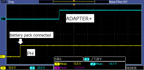
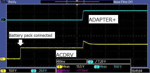
2. ADAPTER voltage is supplied. BATFET is turned off. #PG=LOW and #STAT1=LOW.
3. HIDRV and LODRV does not make any pulse. (When charging working, HIDRV and LODRV make pulse.)
Is the BQ24610 in some fault state or is it broken?
Hi Fuji,
What is status of STAT1 and STAT2? These indicate if charger is in normal operation, or reports faults. The table of possible faults are indicated in Table 2. STAT Pin Definition for bq2461x of the datasheet.
Hi Kedar.
Thank you for your support.
> What is status of STAT1 and STAT2?
STAT1 is LOW and STAT2 is Hi-Z. (LEDs are connected to STAT1, STAT2 and PG)
> 1.What is measured TS voltage?
1.65V
> What is input voltage supplied by adapter?
24V. I tried to change supplied voltages, 20V, 18V and 22V, the behaviors don't change.
> Can you share schematic for me to review?
I attached it. In my test, GNDPWR and J1-#2(BATTERY PACK-) are shorted because I'd like to reject the influence of the balancing circuit (page.2). The balancing connector of battery pack is not connected and BQ77915 is kept in HIB mode. (SW1 and SW2 are opend.)
> Can you take a waveform of VCC, REGN, PH and ACDRV when adapter is plugged in?
I took waveforms.
Hi Kedar.
Could you find anything wrong about our circuit ? I'd appreciate it if you could give us some advice.
Now I wonder NMOSFETs connected to HIDRV and LODRV are not enough tough or not. (In our circuit, those FETs are Q6 and Q7)
So, I removed those FETs and checked resistances of some ports.
The resistance between PH and HIDRV is about 40 ohm. Is it normal ?
If NMOSFETs connected to HIDRV and LODRV were broken, is it possible to break HIDRV or LODRV ports ?
Hi Fuji,
BQ24610 portion of the schematic looks good. When charge stops, what is voltage of ISET1, and can you also take a scope capture of SRN, PH, charge current? I want to see whether battery protector in the system is isolating the battery from being sensed on SRN. What is the purpose of LM9061 in the schematic? For your charge current, the FET you use should be good.
Hi Kedar.
Thank you for checking our schematic.
As I wrote here first, the board does not work now. (Charging will not start.)
> What is the purpose of LM9061 in the schematic? For your charge current, the FET you use should be good.
I want to use NMOSFET as the FET controlled by #BATDRV. It is because the battery current is large (15A).
LM9061 drives NMOSFET(Q8)'s gate.
If you concern about that FET, please teach me.
Hi Fuji,
Looking at your scope capture showing PH:
Hi Kedar,
Thank you for your reply.
I'd like to confirm 2 points.
Point 1. In fault conditions you mentioned, is STAT1 low or Hi-Z?
I checked my circuit, STAT1 is LOW but HIDRV did not start switching.
And other fault conditions did not occur.
TS voltage is 1.65V.
Disabling timer fault (pulled up TTC to VREF) did not effect.
Input voltage (VCC) is 24V and battery voltage is 15.5V.
Point 2.
About "the VCC voltage should be passed on to PH.", I think VCC does not pass PH when Q6 is off (HIDRV = PH).
Do you mean Q6 is ON when adapter is connected ?
I ordered BQ24610EVM and I will check some differences.
Hi Fuji,
Apologize for the typo. For VCC voltage, I was looking to make sure that ACDRV fully turns on the ACFETs, which is why I wanted to verify voltage seen at drain of HSFET. If HSFET is off, then yes VCC will not pass on to PH. Please update if there is issue with results from EVM.