This thread has been locked.

If you have a related question, please click the "Ask a related question" button in the top right corner. The newly created question will be automatically linked to this question.

TPS2121EVM-023: Voltage and Current observed Vin1 when voltage is applied at Vout

Part Number: TPS2121EVM-023
Other Parts Discussed in Thread: TPS2121, TPS2120, TPS2115A, TPS2114A

Use case:

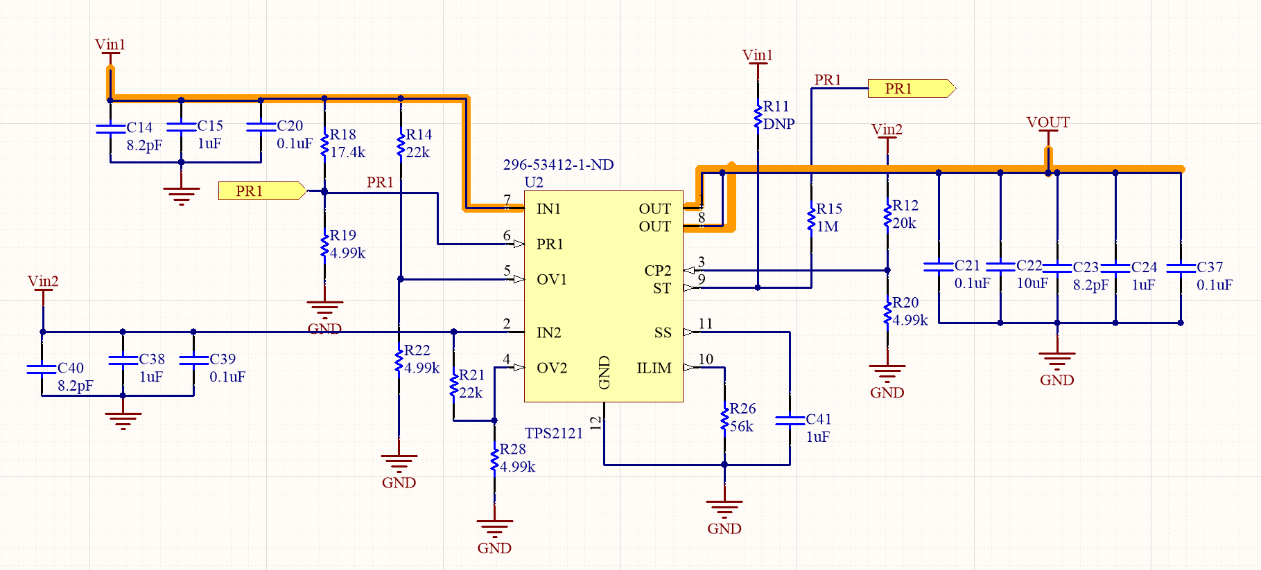
Vin1 vs Vin2 prioritizing Vin1.

Steps to Reproduce:

1. Supply both VIN1 and VOUT with 5V

2. Disconnect supply for VIN1. 

Observation:

1.VIN1 will maintain voltage 5V even when disconnected.

Question: 

Is there a way to configure TPS2121 such that when supply for Vin1 is removed, Vin1 voltage = low?


Thanks,

Leo

  • Hi Leo,

    I am not sure what you mean by: VIN1 will maintain voltage 5V even when disconnected.

    When you disconnect the voltage input from VIN1, The input capacitors on VIN1 have to be discharged. What is the load current in this use case? The device will only switch from VIN1 to VIN2 when PR1<CP2. 

    I also see that you are trying to use the device in fast switchover mode. For this mode, PR1 and CP2 both have to be greater than VREF. Right now, your CP2 value is 0.99V which is insufficient. You are also not using any hysteresis with the ST pin.  I would highly recommend looking at the 5V resistor divider network and R_hysteresis in the EVM user guide: http://www.ti.com/lit/ug/slvubd2a/slvubd2a.pdf

    I would also recommend reading about hysteresis from this TI Design: http://www.ti.com/lit/ug/tidue50/tidue50.pdf

    Please retry the switchover test when you have made the necessary changes. Please share a few scopeshots of the switchover event if you then require further assistance. I would like to see IN1, IN2, ST and VOUT. I would also like to see PR1, CP2, ST and VOUT.

  • The schematic value was not updated from initial draft. Load current approx 500mA testing using EVM board. 

    Vin1 = 4.5V (testing on EVM)
    Vin2 = 5.0V (testing on EVM)

    R12 = 18k
    R18 = 15k 

    ST pin is using hysteresis, R11 pullup is DNP. In EVM board, is connected to pins 1 and 2

    Switchover is correct and work as expected. Only issue is we have a third source (VIN_3 assume 4.5V) connected to Vout (assuming voltage blocking of TPS2121).

    We find that when nothing is turned on, (Vin1 and Vin2 = 0V), and VIN_3 = Vout = 4.5V. Vin1 and Vin2 = 0V that is correct, and expected.


    But if Vin1, Vin2 and Vin3 voltages are supplied, and then we stop supplying for Vin1 and Vin2, we find that Vin1 Voltage = Vin_3.
    We tried a weak pulldown (100k, 10k, 1k) attached to Vin1, but its not due to charge from caps. 


    Thanks,
    Leona

  • Leona,

    Are you testing the reverse current blocking?

    RCB will only trigger once the reverse current triggers I_RCB. Please refer to Section 9.3.6 in the datasheet. 

    If there is no reverse current the channel will remain ON.

  • Yes.

    We we find that when reverse blocking is enabled, triggered when Vout > Vin1, in order to get Vin1 to go back to 0V Vin1  need to draw more than 200mA. 

    Its a special use case, for sure. But is there a way to reduce I_RCA that? Or is there an alternative part that has lower I_RCA?

    Thanks,

    Leona

  • Hi Leona,

    Unfortunately, there is no way to reduce this IRCB threshold. This value of 200mA is expected for TPS2121 and TPS2120.

    TPS2114A and TPS2115A also do have reverse current blocking ability but this comes at the cost of switching speed, current capability and package size. These devices may fit your use case better.

    Apologies for the inconvenience. Thank you for choosing TI Power Switches for your designs.