This thread has been locked.

If you have a related question, please click the "Ask a related question" button in the top right corner. The newly created question will be automatically linked to this question.

UCC28700: Non-isolated buck converter with high input voltage

Part Number: UCC28700
Other Parts Discussed in Thread: PMP10739, PMP

Hi,

I'm a FAE for TI products.
I have been asked by a customer if there is a device that can support the following specifications:
As for the configuration, I think the reference design PMP10739 using UCC28700 is good.
Is it possible to satisfy customer specifications with this configuration?
Also, it would be helpful if you could tell me any other good configurations.
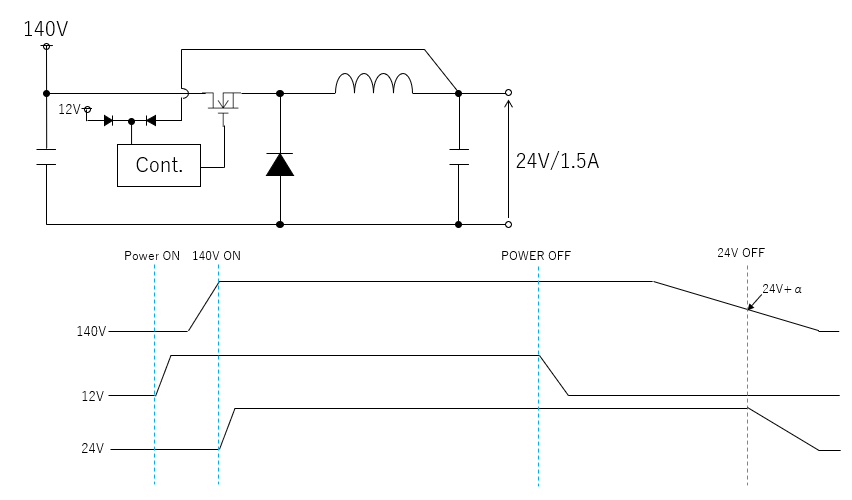
(specification)
VIN : 140V DC
VOUT : 24V
IOUT : 1.5A
* Composed of non-isolated.
* Apply 12V from outside. There is a power supply sequence in this case.
Best regards,
  • Hello Kaji-san,


    Thank you for your interest in the UCC28700 flyback controller.


    The UCC28700 controller design is generally intended for off-line, isolated discontinuous-mode (DCM) flyback applications. It has features and thresholds targeted for such use. The PMP10739 reference design adapts this controller to a non-isolated 3.6-W DCM buck topology.


    In principle, the buck adaptation shown in PMP10739 reference design should be applicable to a 36-W power level as well. There are several practicable issues and limitations to consider:


    1. This controller cannot operate in CCM, so the inductor current must still be DCM (similar to those shown in the PMP10739 Test Report document https://www.ti.com/lit/ug/tiduaq5/tiduaq5.pdf, pages 8-9).  

    2. This controller limits the demagnetization duty-cycle (Dmagcc, see datasheet page 20) to 0.425 to provide constant current regulation, which indirectly forces the peak secondary current to be >4.7 x Iout (in this case ~7Apk).

    3. Designed for start-up from an off-line bulk voltage, the VDD turn-on threshold of the IC is 21V. If only 12V is provided externally, this controller will not start up. The external bias supply must be brought up to >21V first, then can be reduced to 12V. The PMP design incorporates the start-up bias with R8 and R9 network. Given the start-up timing in your diagram, the 36-W design can achieve the same thing without using an external 12-V source.  In the timing diagram, even if 12V is provided, the 24-V output is not active until the 140-V source is turned on.   This is the same situation as in the PMP10739 design.

    4. At the 12-V power off point, the 24-V output continues to regulate as long as 140V is on. This is the same situation as with the PMP design. VDD bias is maintained from the output voltage through D1 and D2. Therefore, based on this timing, the 12-V external bias source is unnecessary.

    5. Converter start-up and shut-down points are determined by the Rs1 value (R1 in PMP10739). This is not the same as IC start-up. The IC starts after VDD has reached 21V. Once the IC starts, it will attempt to start up the converter and will test the VS current set by Rs1 (see datasheet page 19, equation 15). In this non-isolated DCM-buck adaptation, Eqn 15 must be modified to Rs1 = Vin(run)/Ivsl(run), where Vin(run) is the minimum input dc voltage level at which the converter should start to run. (For a fixed 140-V bulk source, you can choose Vin(run) = 120Vdc, for example, to account for tolerances.)

    6. Converter shut-down, based on bulk voltage level, is not independent of the Run voltage setting, nor of the Dmagcc constant. The timing diagram shows 24V output operating with Vin down to (24V + alpha). With the constraint of volt-second balance Vin*ton = Vout*toff. Changing to duty cycles, Vin*Don = Vout*Dmagcc, so Vin = Vout*Dmagcc/(1-Dmagcc) (approximately, neglecting the resonant ring time). Since Dmagcc is fixed at 0.425 maximum, Vout would fall out of regulation when Vin reduces to ~18V. However, the Ivsl(stop) current is 0.36 of the Ivsl(run) current, so the converter will stop switching sooner, when Vin falls to 0.36 * 120V = ~44Vdc in this example.  


      If any of these limitations and considerations is unacceptable, I suggest investigating other controllers that may be recommended by TI’s Webench Power Designer tool or the Power Stage Designer tool, both found at https://www.ti.com/design-resources/design-tools-simulation.html. Your input and output conditions can be entered and these tools will generate a variety of designs with different controllers that may be more suitable than the UCC28700.


      Regards,
      Ulrich