This thread has been locked.

If you have a related question, please click the "Ask a related question" button in the top right corner. The newly created question will be automatically linked to this question.

LMZ13608: LMZ13608 Enable Pin voltage

Part Number: LMZ13608

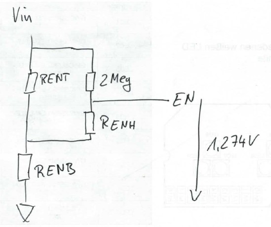
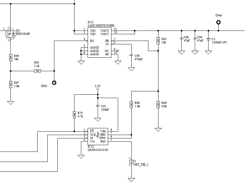
I tried to set UVLO and hysteresis based on the figure 48 of the data sheet. I am using 56K for RENT, 5.6k for RENB and 2.2k for RENH.

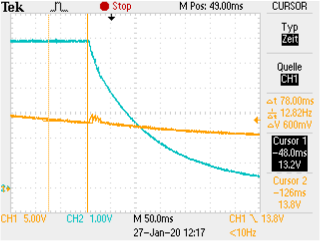
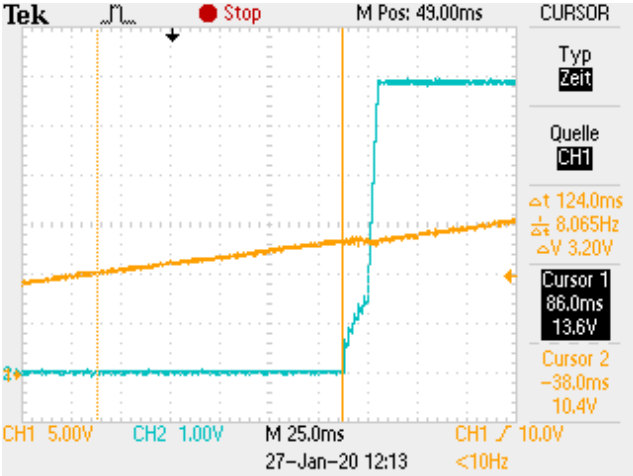
Measuring the circuit I found that I do not get the expected values for the threshold and hysteresis, and it seems that the EN pin does not source the 13uA when the device is enabled. I found that the pin sinks between 7uA and 15uA depending on the voltage at Vin.

Am I missing something, or is there an issue with the datasheet?

  • Hi Jottm,

    Can you provide your design condition (input,output,load) so I can have a better understanding of your application? Are you running in ambient temperature condition (25C)? 

    Regards,

    Jimmy 

  • Hello Jimmy,

    I got an email where your answer is different to the text above, there is the additional sentence:

    "From my calculation with your values, you should have a Ven_rise of 14V, and Ven_fall of 13.6V using RENT = 56k, RENB=5.6k, RENH=2.2k. "

    From my measurement I got Ven_rise of 14.2V which may be OK but I got Ven_fall of 10.8V what seems to low.

    The design is indented to work with typ. 24V input and 5.6V output and 3.4A load. For the measurement of the enable voltage I used a different load of 33 Ohms.

    I tried to calculate the thresholds using the formular (2) and (3) on page 18 but I there must be some mistake because I get results of Ven_rise of 13.7V and Ven_fall of 13.6V. Maybe you could explain how you calculated the results, I am not sure if I used the formular correct.

    I created a test point for production at the Ven pin, the expected voltage at the pin with 24V input was 2,35V using a 10MOhm voltmeter. What I see is only about 2.24V.

    Best regards

  • Hello Jottm,

    I will let Jimmy comment on the measurement/calculations. He is out of the office today, but please expect a reply on Monday.

    In the meantime, the Ven_fall of 10.8V you measured does seem a bit low for the mentioned resistor values.

    Can you confirm the EN pin voltage when the part shuts off?

    Do you have an oscilloscope screenshot of the VIN, EN, VOUT voltages?

    Also, are you measuring VIN at the module VIN pin with respect to the module GND terminal?

    Cheers,

    Denislav

  • Hello Denislav,

    I made the first measurement with a manual voltage sweep and a multimeter for the output voltage.

    Today I made a measurement with a SMU and an oscilloscope, this results in 13.2V Ven_fall and 13.6V Ven_rise, maybe there was a bad synchronisation between may hand turning the power supplies voltage setting and my reading of the multimeter with the first manual measurement.

    Given the accuracy of the oscilloscope voltage reading the new results look better. The screenshots show Vin on channel 1 and vout on channel 2.

    I am still wondering about the Ven pin voltage range that could be expected with an 24V input voltage, I checked that again and got the same value of 2.24V.

    Best regards

  • Hi Jottm,

    I had to edit my answer because my calculation had an error so I decided to create a UVLO spreadsheet for the LMZ13608. Please have a look at the spreadsheet below.

    Hysteresis_UVLO_Calculator_LMZ13608_10.xlsx

    With the values you are using right now, the resulting Ven_rise is around 13.67V and Ven_fall around 13.57V. The Ven_fall can be configured by changing the Renh resistor value. This may explain why you are seeing the Ven_rise and Ven_fall that is similar to my calculations. 

    Regards.

    Jimmy 

  • Hi Jottm,

    Can you also provide a picture of your schematic. When you mention handtuning, are you referring to a resistor pot? 

    Given my excel spreadsheet calculator, the RENH resistor would have to be 30kOhm for it to result in a Ven_falling of 13.2V. 

    Regards,

    Jimmy 

  • Hello Jimmy,

    the hand turning I mentioned was when I checked the thresholds for the first time. I used a lab power supply and turned the voltage setting of that supply from 10V to 20V to check when the LMZ13608 starts. There is no resistor pot in the circuit.

    I think the formular for the rising threshold in the datasheet and in your excel spreadsheet is not correct. When using the internal 2meg in the calculation we must also consider Renh also for the rising threshold, especially when using larger values as 30kOhm. Do you agree? Please have a look at the following circuit.

    Below the schematic of the LMZ13608 you asked for.

    Q3 was always on for my tests, it is used to switch the supply from a mcu. The MCP41010 is a digital pot we use to adjust the output voltage. It has a fixed setting in my tests.

    Best regards

  • Hi Jottm,

    Thank you for pointing this out. Let me contact the apps engineer who wrote the datasheet to get a better understanding of the equation. When i get more information on this, I'll get back to you asap. 

    Regards,

    Jimmy 

  • Hi Jottm,

    Please be aware that I am still trying to get information on the equation in this datasheet. This is a relatively old part so it is a bit hard to track down the the right engineer who is currently responsible for it. However, I do think that the RENH resistor should be accounted for in the Ven_rising equation since it is part of the overall resistor circuit that defines the rising threshold. 

    I would guess the reason it was not included in the datasheet was because the value was assumed to be significantly smaller than Rent. However, as you pointed out, this resistor will come into affect when you begin increasing it to 10kOhms and above. 

    Again when I get anymore information on this, I will get back to you. Thank you for your patience. 

    Regards,

    Jimmy 

  • Hi Jottm,

    I was not able to get any additional information on this. However, I do agreed that the RENH resistor would come into play if its value is higher and becomes considerable around 10k and above. 

    Regards,

    Jimmy