This thread has been locked.

If you have a related question, please click the "Ask a related question" button in the top right corner. The newly created question will be automatically linked to this question.

UCC28730EVM-552: UCC28730EVM-552: required bulk capacitance much higher than recommandation

Part Number: UCC28730EVM-552
Other Parts Discussed in Thread: UCC28730, UCC24610, CSD18534Q5A, UCC24612

Hi,

We have modified the EVM to create a 12V/4W AC/DC power supply. (see excell file)

For the Vs measure we have: 127k (R2) / 59k (R3)

For the Vcs measure we have Rcs = 3.3Ohms (R9/R11/R12), Rlc = 4.7k

the transformer is a 750841034 from wurth (1.1mH 6:1:1)

It is working fine with 2x10µF bulk capaticitance (see VS and Vcs below under 50Ohm load):

Vs

Vcs

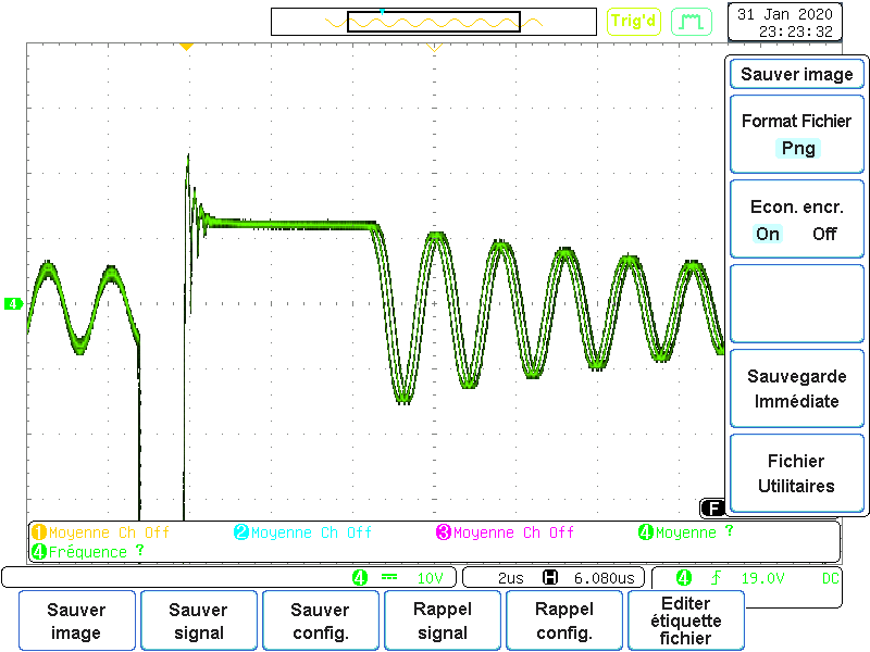
but the current measure is already high than recommendations (but ower than the 1.5V limit).

Why is it that the lower the bulk capacitance is, the higher the current pic is? There is nothing about that in the datasheet. The spreadsheet gives a required 2µF of bulk capacitance, the datasheet advise 2µF per watt, but you cannot get the current below the 1.5V threshold unless you have more than 20µF of bulk capaticance (whatever the Rcs resistor is, for example, with these parameters, Vcs=3V under no load or load condition, so there is 3 pics and the device resets). There is almost no drop on Vbulk (1V/380V)


many thanks for your advices!SLUC579_UCC28730 Design Calculator 12V.xlsx

  • Hello Romain,


    Thank you for your interest in the UCC28730 PSR Flyback controller and its EVM.


    I’m not sure why you are seeing higher peak currents with lower bulk capacitance.   The current peaks are determined by the Vcst level commanded by the control law of the UCC28730 for the given set of input and output conditions.   These I/O conditions are measured at the VS and CS inputs, as you know.


    However, the waveforms you show are not at VS and CS. The waveforms labeled “Vs” are actually the Vaux winding waveform. This is good practice, because directly probing the VS pin adds capacitance which would deteriorate the VS signal and interfere with proper regulation and timing.


    The waveform labeled Vcs is measured at the sense resistors R9/11/12. The controller acts on the signal that it sees at the CS input. This signal is filtered by R7 (Rlc, now 4.7K) and C5 (27pF). This filter will suppress the sharp peaky shape of the Rcs waveform, but also adds a delay time of 127ns to the signal.


    At your 50-ohm load level, operation is in the upper FM band and Vsct(max) = 0.74V. The controller will turn off gate drive when it sees Vcs cross 0.74V, but this signal is delayed by 127 ns, so VRcs continues to rise above the 0.74V level. The down-ward notch in the slope of VRcs indicates when the GATE output voltage drops and pulls current out of the MOSFET gate. Actual VRcs has reached 0.8V by then.

    I believe that the sharp narrow peak after that notch is the effect of capacitive coupling to the probe by the drain dv/dt at turn-off.   I don’t think that it is real current, only noise. Use a “tip-and-barrel” probing technique to minimize this noise.


    Having said all that, there may be additional issues that are affecting start-up on your modified EVM.

    I assume that the output SR-FET and controller UCC24610 are still connected, since you did not mention disconnecting them.  These parts were chosen for a 5V output with a transformer with a ~12:1 turns ratio. You have changed to a 6:1 ratio with 12V output. 380V bulk reflects as 63V +12V = 75V max reverse voltage.    The UCC24610 VD pin is rated for only 55Vmax with respect to GND. The SR MOSFET CSD18534Q5A is rated for only 60V. I suspect that one or both of these devices became damaged or destroyed once you raised the input voltage high enough.


    When the SR-Fet becomes a short-circuit, then the primary current peaks are always exceed the Vocp threshold (1.5V) and higher because of the turn-off delay.


    Please check your design to see if you need to replace the SR-FET with a higher rated part and substitute the UCC24612 controller in place of the UCC24610 (they are not the same package, unfortunately).


    Regards,
    Ulrich

  • I forgot to mention that everything is removed on the secondary side. Took me a while (a full week in fact...) to notice that the capacitor were rated 6.3V so now i only have the SR-FET wth grounded gate and a 100µF 63V capacitor. I can try to replace the SR-FET too.

    The board is still working if i put the 2x10µF input capacitor back in place. I will capture the current peaks for 2x2.2µF, 2x4.7µF and 2x10µF (new one to check if it s working)

    your guess is that the switching is too slow, i will remove C5 again (i have done it already doesn't help me much) maybe try to populate D5 to get a faster switch off? Maybe a faster switch?

    Thanks for the advices, i will keep you informed.

    Best regards

    Romain

  • Hello Romain,

    I haven't seen a follow-up post since Feb 6th, so I will close this thread. If you need more help on this issue, you can re-open it, or start a new thread.

    Regards,
    Ulrich