This thread has been locked.

If you have a related question, please click the "Ask a related question" button in the top right corner. The newly created question will be automatically linked to this question.

LM320-N: Excessive Output Noise Voltage

Part Number: LM320-N
Other Parts Discussed in Thread: LM340, LM2990
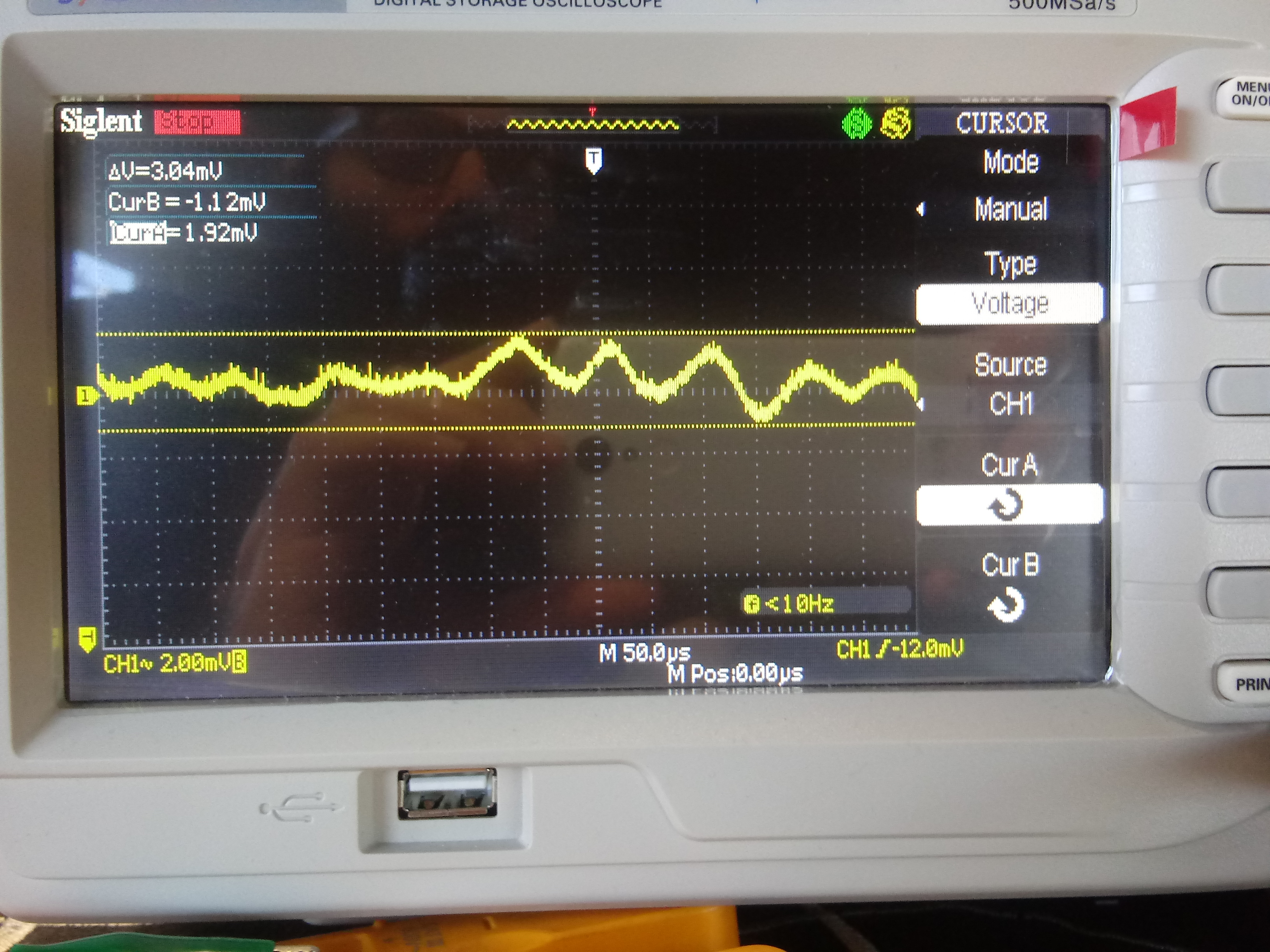
We are measuring 3mV of Output Noise Voltage on the LM320T-15 Negative Fixed Voltage Regulator instead of the 400uV suggested in the datasheet.
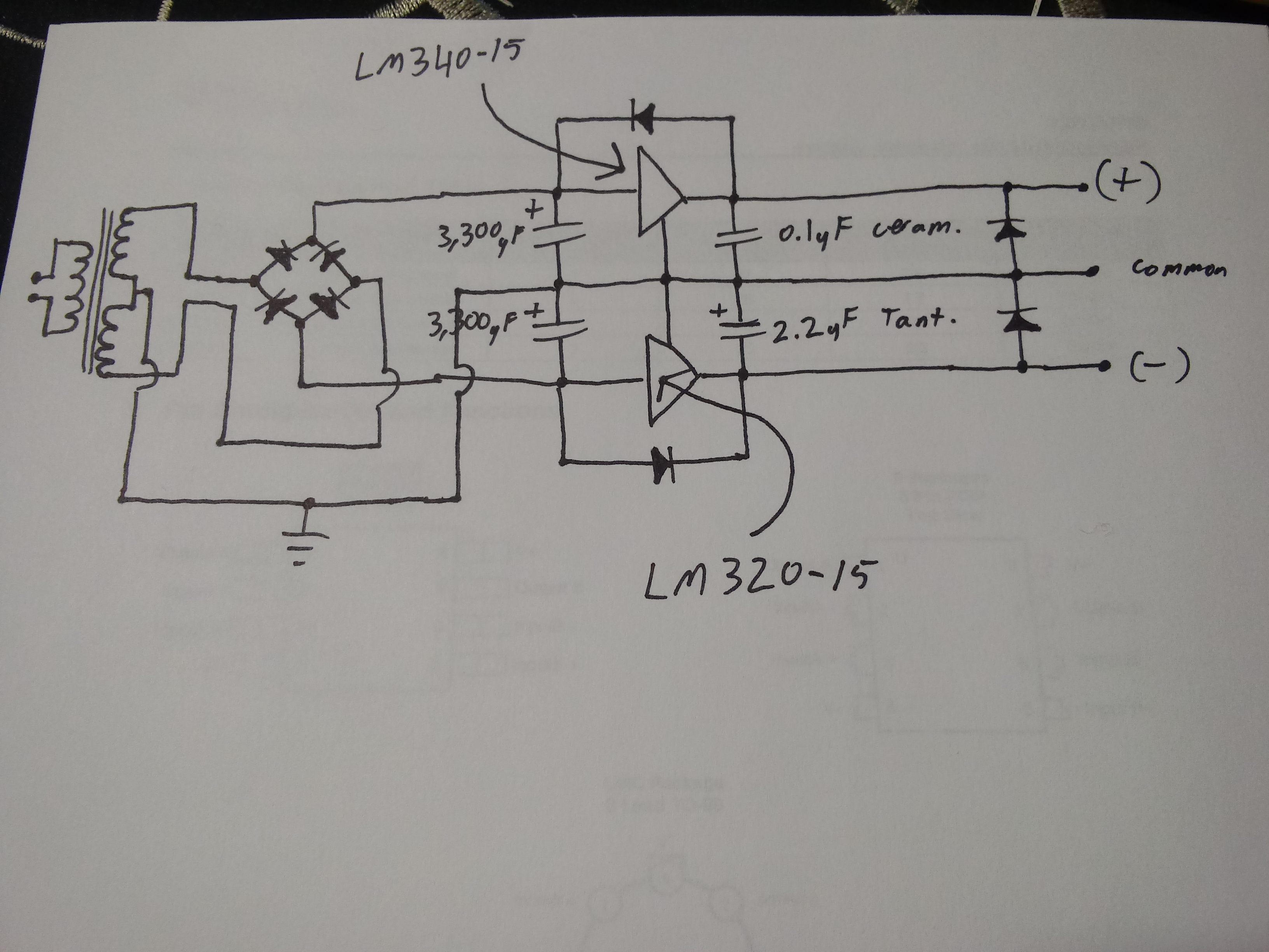
As you can see, this is a bipolar power supply which uses the LM320-15 and LM340-15 fixed voltage regulators. The LM340 is working just fine and exhibiting noise voltage levels consistent with the data sheet.
This noise is difficult to trigger and measure since it is fluctuating, although it is around 11khz during a no-load condition. The frequency increases with load.
We have tried to increase the value of the output tantalum capacitor from 2.2uF up to 22uF and this made practically no difference. We also tried ceramic capacitors of various values from 0.1uF to 1uF also with no practical affect. We also tried electrolytic capacitors from 10uF to 2200uF, and the higher 2200uF value was the only output capacitor value that reduced this noise to the suggested levels. Though this was just to test, and will be impractical to employ a large capacitor in the final design (power supply for ultrasonic amplifier in museum exhibition).
As you can see, the large input filter capacitors are about 1 inch ahead of the regulator (as suggested), and we have employed reverse bias protection diodes. I would like to state that we are not measuring any of this noise on the input side of the LM320 regulator. On the input side of the LM320, we can only see the expected 120Hz rectifier ripple with no other frequency components. Also to note, the voltage drop occurring within the regulator (from the highest point in the input ripple, to the target -15 VDC) is 8 VDC, and this rectifier ripple is effectively reduced on the output of the LM320 just as the datasheet suggest an 80dB reduction in PSR. It is just this 3mV of noise which is unexpected.
We have also tried to replace the chip with another unit in case it was a defective part, but the results were the same.
This leads us to believe that this oscillation is a product of an inappropriate output capacitor ESR value. Though the datasheet for the LM320 does not make any ESR recommendations for the output stabilizing capacitor besides a simple minimum capacitance value. We have noticed that the datasheet for the LM2990 -15 fixed negative voltage regulator makes particular ESR suggestions for the output stabilization capacitor.
You will find images of our schematic, output noise voltage screen shots of both LM320 and LM340, and the test fixture.
Your help is appreciated.

  • Hi Shant,

    I'm leaning away from ESR as being the culprit at this time.
    These older devices were made in an era where capacitors had very large ESR values.
    Given the range of capacitors you have used (ceramic, tantalum, aluminum electrolytic) it does not appear related to the ESR value.

    Can we look at the layout?
    Are the heat sinks tied to RTN of the LDO, or chassis?
    Is there a ground plane tied to common underneath the LDO capacitors and diodes?

    What is the minimum load (current) you have tested with?

    Thanks,

    - Stephen

  • Hello Stephen,

    The heat sinks are electrically isolated from RTN (The tab on the chip is electrically insulated from the heat sink). Also, the heat sinks are not connected to ground.

    I have not used a ground plane in order to use a star grounding scheme. Although the capacitors and diodes do have a low impedance connection to common, it is not through a ground plane.

    The lowest load Ive measured noise under (besides 0 load) was 1.5mA. No change was detected in comparison to 0 mA. At larger loads, the frequency of the noise increases, but the 3 mV p-p remains about constant.

    How can I send you the board layout images?

    Thank you,

    Shant K.

  • Hi Shant,

    I have sent you a 'friend' request through E2E.
    If you accept, you should be able to send me the files directly.

    Does the noise go away with 5mA of load current?
    Or does the frequency just shift?

    This may also be the result of noise coupling.
    If noise couples into the GND of the LDO, it will ride on that noise.
    Normally GND is a large plane with a very low impedance, however it may not be in this case.

    It looks like the heat sinks are electrically isolated from common and the LDO ground terminal.
    They can act as antenna's to couple radiated noise.
    Capacitive coupling can then occur from the heat sink to the LDO.

    A ground plane will electrically isolate capacitively coupled noise through the PCB layers, if that is the noise coupling mechanism.

    Is it possible to remove the isolation from the LDO ground pad to the heat sink, and see if the noise goes away?

    Thanks,

    - Stephen

  • Hi Stephen,

    The noise does not go away under any load condition. Its frequency just shifts upon loading the regulator.

    I will test the circuit again by coupling the currently floating heat sink to the system common, as well as coupling the heat sink to the tab of the regulator. Which is internally common with power supply (-), not ground.

    I will report results shortly.  Also, I have sent you images of the board layout.

    Regards,

    Shant K.

  • Stephen,

    I have tried bringing the heat sink to the (-) chip input potential, as well as coupling it to the system common. In either case, this problematic noise still remains (in fact, it goes unchanged whatsoever).

    Regards,

    Shant K.

  • Hi Shant,

    Can you provide oscilloscope shots of the input and output voltage of the LDO?

    Thanks,

    - Stephen

  • Stephen,

    The relevant details are as follows.

    LM320-15 linear voltage regulator (to-220 package) (Not low drop out type).

    With 0 mA load on the output

    Input voltage: - 23 VDC with 5 mV p-p power supply ripple @ 120 Hz. No other frequency component.

    Output: 3 mV random noise @ +/- 11 kHz (again, I refer you to the image I've enclosed above)

    With 15 mA load on the output

    Input voltage: - 23 VDC with 40 mV p-p power supply ripple @ 120 Hz. No other frequency component.

    Output: 3 mV random noise with multiple frequency components between 11 - 100 kHz

    Regards,

    Shant K.

  • Hi Shant,

    I have two comments that may be helpful going forward.

    1. The oscilloscope probe may be acting as an antenna picking up noise.
    It is not hard to couple noise at the milivolt level into an oscilloscope probe.
    I would at least confirm that swapping oscilloscope channels does not improve the measurement.
    I would also make sure that the environment around the test setup is as noise free as possible, to eliminate the possibility that noise is being picked up.
    For instance, electromagnetic field coupling can occur between the wires of the bench supply and the oscilloscope probe if they are close to each other.
    So routing them away might help.  Bench top power supplies are known to have switching frequencies in the dozens of kilohertz in many cases.
    Also move any cell phones or other noise devices away from the oscilloscope and PCB during the measurement.

    2. The star grounding may be affecting the measurement.
    I have used star grounding successfully in system level grounding schemes.
    Examples are entire subsystems, or rack mounted test equipment that must connect chassis connections together.
    At a more local level, it may be possible to employ this with different circuit technologies (analog, RF, digital, etc).
    We recommend the shortest loop areas possible for linear regulators, which this particular layout does not achieve.
    As is, the loop area from the output capacitors is large. 

    The output of the LDO travels to the tantalum capacitor positive lead, through the capacitor to the return lead.
    But instead of directly turning back to the LDO, it flows to the center of the board before returning to the LDO.
    This is a correct star formation, but the LDO circuitry should be thought of as a "system".  You will want the input capacitor, output capacitor and LDO to be tightly coupled.  In this way the output of the LDO is "DC" and there is very little trace copper to couple into.  If noise is a critical parameter for the system, you will want a very low impedance directly underneath the noise sensitive circuitry to act as a capacitive shield.  Typically this low impedance is the ground plane of the LDO or power electronics.  The way the layout exists, there is potential for capacitive noise coupling between the PCB layers (traces).  If you tightly couple the input and output capacitors around the LDO's, then treat that as a system - you may be able to use a star formation grounding with success. 

    Thanks,

    - Stephen

  • Stephen,

    Like you suggested, we also believe that the long output capacitor ground track may be causing or contributing to the issue. For this reason we have planned a test to rule that out. I do not believe that the noise is a product of poor measurement techniques, or inadvertently coupled noise since we are not measuring any of this noise on the positive regulator, nor is there any switchmode devices anywhere near the test fixture (besides perhaps within the oscilloscope). Its all linear. I will post test results soon.

    Thank you, 

    Shant K.