This thread has been locked.

If you have a related question, please click the "Ask a related question" button in the top right corner. The newly created question will be automatically linked to this question.

TPS63027EVM-870: Buck/boost Vout=5V@2A, Vin from 2.7V to 5V

Part Number: TPS63027EVM-870
Other Parts Discussed in Thread: TPS63027,

From TPS63027 datasheet results a maximum Vout = 5V, without a clear specification about current. So we bought TPS63027EVM-870  EV board, changing feedback resistors (R1 and R2 in datasheet) according to these three attempts:

ATTEMPT 1: R1 = 430 kOhm, R2 = 82 KOhm;

ATTEMPT 2: R1 = 1000 KOhm, R2 = 180 KOhm (the attempt resulted from datasheet advice to mantain R2 in range of 180 KOhm);

ATTEMPT 3: R1= 523 Kohm, R2 = 100 Kohm (suggested by TI technical support). 

However, the result still remains the same: in output we obtain 4,8 V in all cases (in attempt 2, the resistors sizing lead to Vout = 5,2V !). Besides, with a load of 0.5A, we get this value after a very slow ramp, during at least 1 hour (from a starting Vout = 3.3).

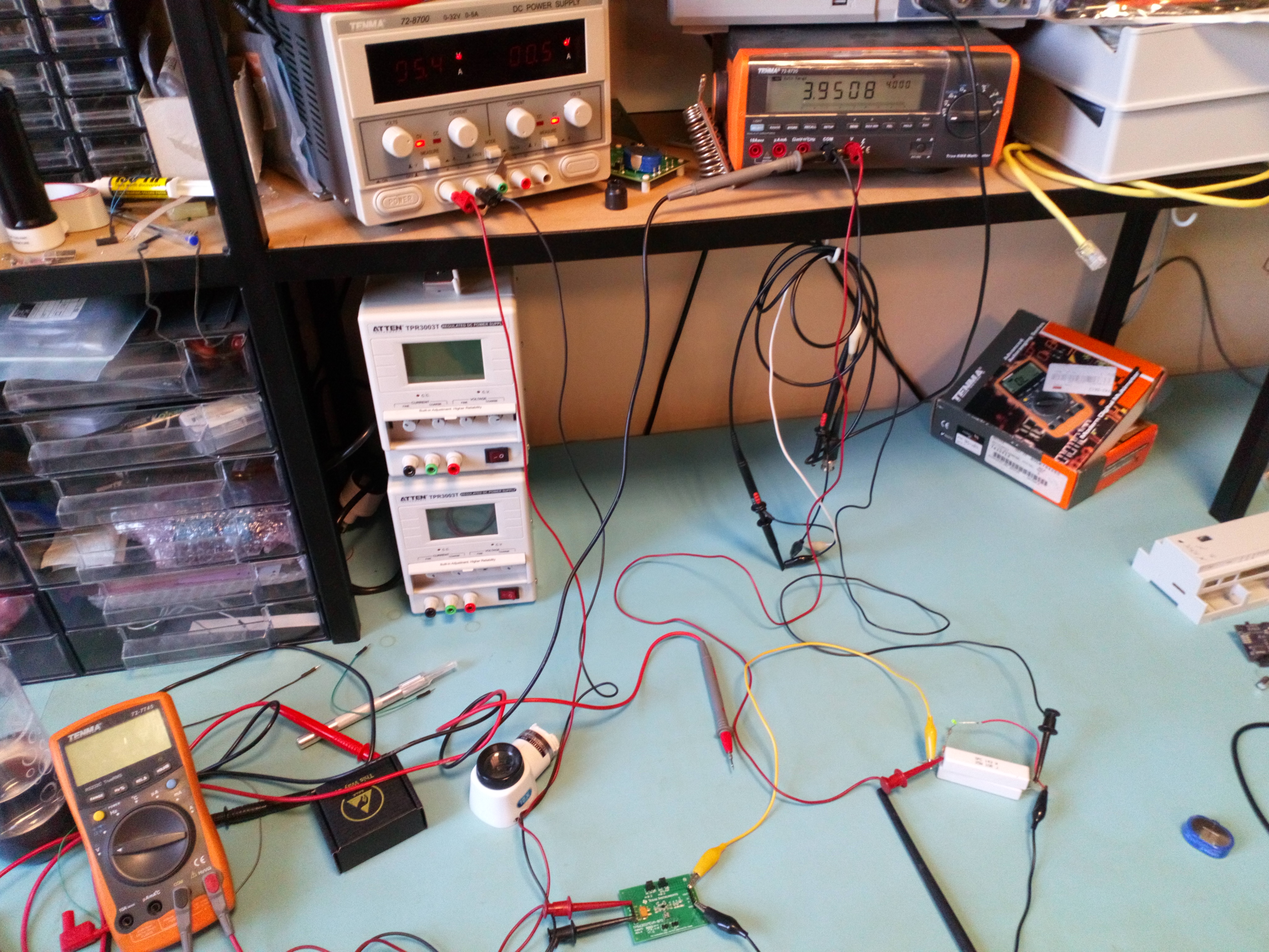
In the setup we provide the supply voltage (from 4.5V to 5.4V) to the board, whose output is connected to 10 Ohm resistors (in photo are shown two resistors in parallel, but we tried also a single resistor. Respectively, outputs current are 1A and 0.5A). The current values lies on datasheet rated range (measured by bench power supply), instead output voltage is measured by bench multimeter.

In conclusion, the trouble is that is obtained a lower voltage than indicated by datasheet (4,8V), through a too much slow ramp (last of two hours, regardless about the load). 
So, in your opinion, how can we fix this?


  • Hi Vito,

    If the device is operating properly, the output voltage should always be:

    Vout = Vref * (1 + R1/R2)

    which is 5 V for your cases 1 and 3, and 5.2 V for case 2. R2 value of 180 kΩ is a compromise between the efficiency at light loads and the output voltage accuracy, please check this article:

    http://www.ti.com/lit/an/slyt469/slyt469.pdf

    Typically, switch mode converters have inrush current during start-up. If your power supply is weak or you have high impedance between the power supply and the EVM, the input voltage will drop and trigger the UVLO, turning off the device. When the device turns off, the input voltage recovers and the cycle repeats, the converter gets stuck in these oscillations or recovers after very long time. See this article for explanation:

    http://www.ti.com/lit/an/slyt730/slyt730.pdf

    Looking at your setup, I suggest:

    1. Check if you have current limit turned on on your power supply, and connect the EVM to the power supply with short and thick wires. 
    2. Try turning on the EVM without load, to confirm the output voltage is 5 V, using the default R1 and R2 values.
    3. You are measuring the output voltage directly on the load, therefore you include the voltage drop in your wires. Use thick and short wires for your load, and measure the output voltage on the header J5 on the EVM.

    Best regards,
    Milos

  • Hi Vito,

    We haven’t heard back so we're assuming this resolves your issue. If not, just post a reply below, or create a new thread if the thread has locked due to time-out.

    Thanks and regards,
    Milos