Other Parts Discussed in Thread: TPS61175, TLV61048, TLV61046, TPS61099
Hi, I used the WEBENCH
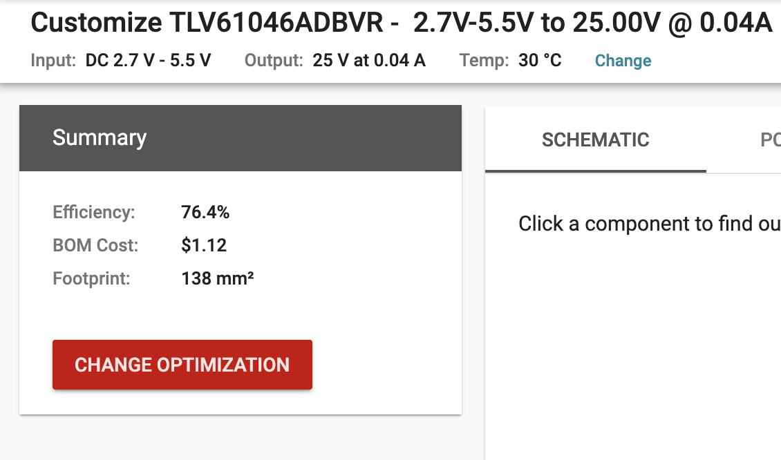
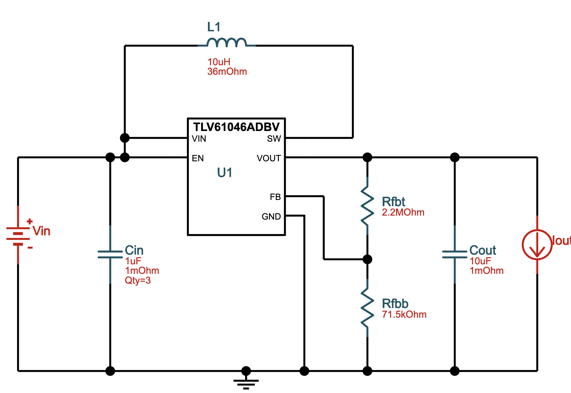
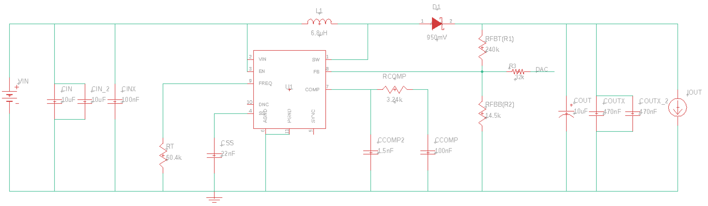
and simulated this.
The input will be
Lithium Ion Polymer Battery - 3.7v 500mAh
in order to create 25V (max current 40mA).
May I ask
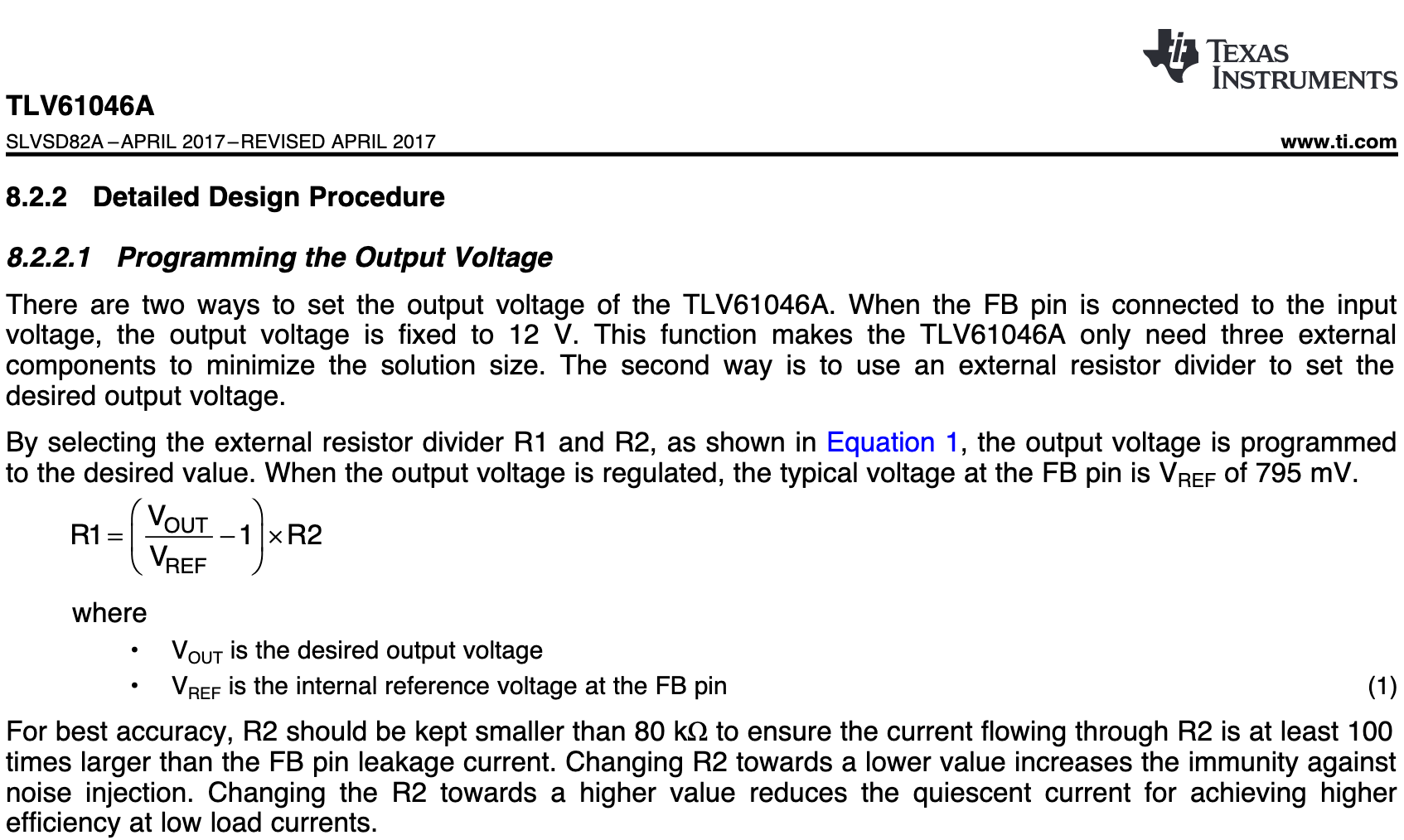
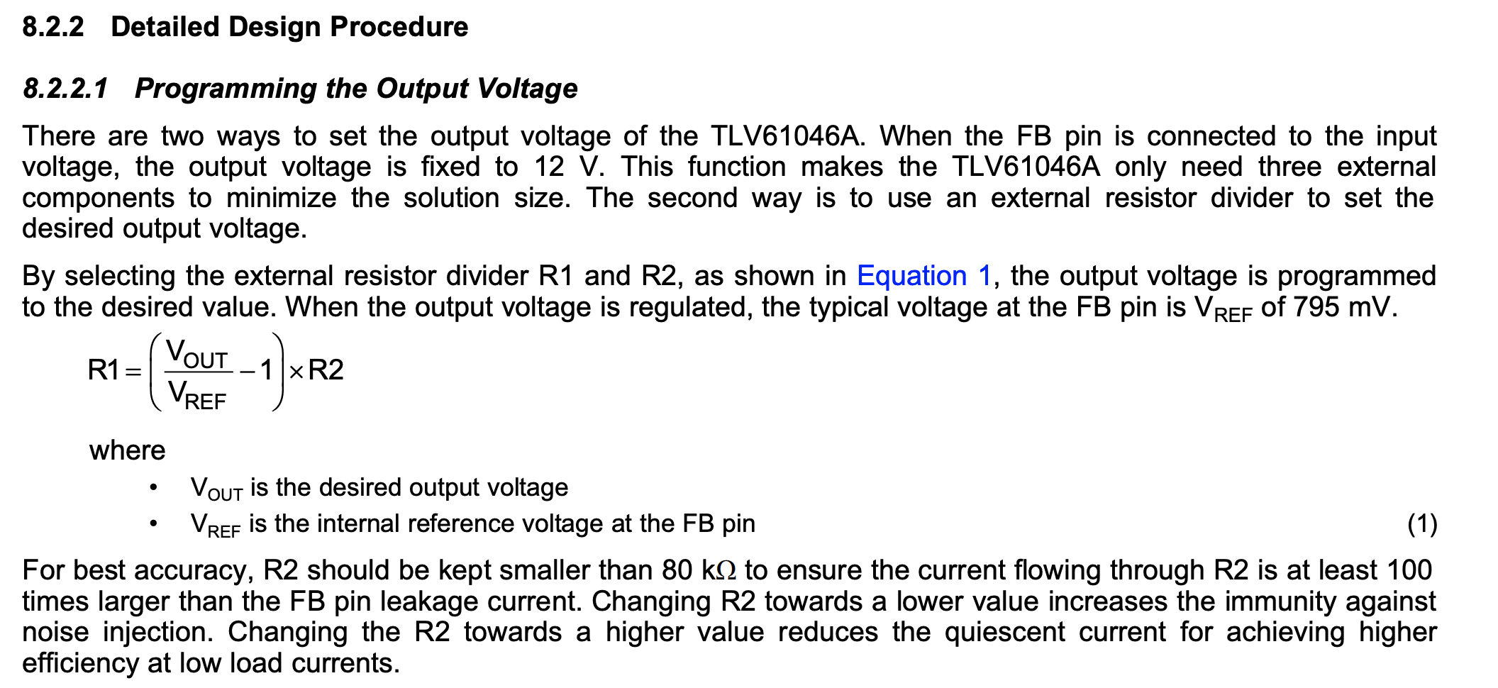
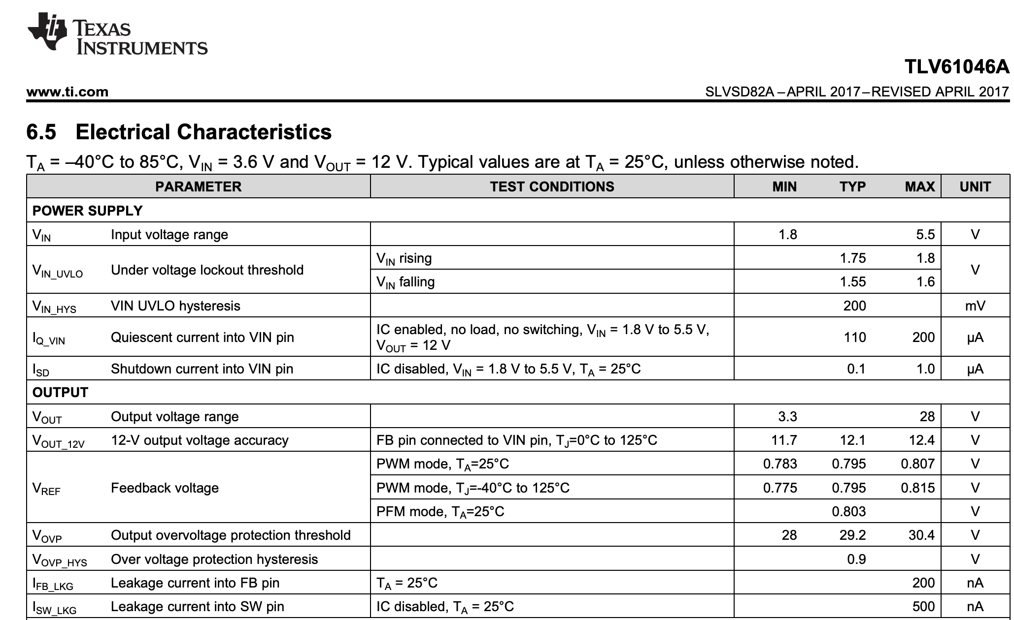
q0. the TLV61046A's FB pin creates 0.795V, right?
Since other products like TPS61175 had VFB = 1.229V, I wanted to double check.
q1. considering the LiPo input, can I apply equations from PMP15037 so that I can control TLV61046A's output?
I'm considering a MSP430G2 lauchpad's PWM or Arduino DUE's DAC for testing this.
Since it says "R2 should be kept smaller than 80 kΩ to ensure the current flowing through R2 is at least 100 times larger than the FB pin leakage current.",
using the PMP15037 seems to be the problem for me.