This thread has been locked.
If you have a related question, please click the "Ask a related question" button in the top right corner. The newly created question will be automatically linked to this question.
I am currently using 3-phase bridge drivers for the IGBTs of the inverter stage of a BLDC motor.
Why should I consider a gate driver to replace the 3-phase bridge driver in my existing solution? What are some performance advantages of the half-bridge gate drivers over my current solution?
Why should I replace 3-phase bridge drivers with half-bridge drivers in automotive AC compressor modules?
High-voltage 3-phase BLDC motors are used to drive the AC compressor in high-voltage HEV/EV. HVAC compressors, which can require 10 kW of power, are second only to traction motors in terms of power consumption.
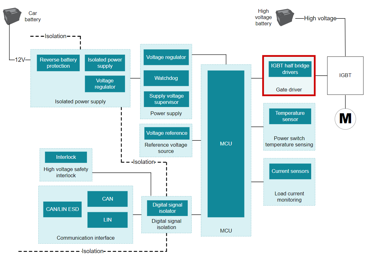
Figure 1 shows a typical AC compressor module block diagram with IGBTs as the inverter stage to drive the 3-phase BLDC motor. An inverter stage consists of three pairs of high-side and low-side IGBTs configured in half-bridge topology.
Figure 1: Block diagram of an automotive high voltage HVAC compressor module
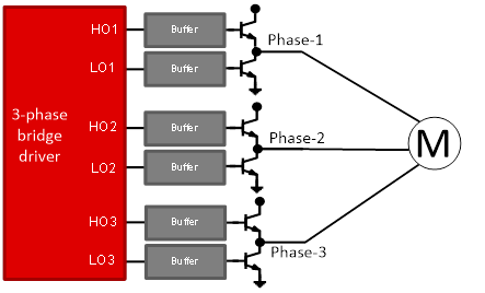
As shown in Figure 2, designers have the choice of using 3-phase bridge drivers IC’s to drive the IGBT’s of the inverter stage. However, because of their low drive strength of <500 mA, 3-phase bridge driver solutions typically require additional buffers to act as a current booster. This means additional components, which translates into additional cost, system PCB size increase and performance degradation (EMI risks and increased propagation delays) of the overall system as a result of parasitics from a non-ideal PCB layout.
Figure 2: Driving the inverter stage with 3-phase gate drivers
To help minimize switching losses from the IGBTs and reduce EMI for higher system efficiency, designers have the choice of using half-bridge gate drivers to drive each phase of the inverter stage instead. That is, the 3-phase bridge drivers depicted in Figure 2 are increasingly being replaced with half-bridge drivers such as UCC27712-Q1 as shown in Figure 3.
Figure 3: Driving the inverter stage with three half-bridge gate drivers
The following are the reasons for using TI half-bridge drivers to drive the IGBTs:
Table 1 below highlights some of the key performance advantages of the UCC27712-Q1 half-bridge gate driver over some 3-phase bridge drivers.
Common 3-phase bridge drivers |
||
Peak output current (A) |
>1 |
<0.5 |
Rise time (ns) |
<20 |
>100 |
Fall time (ns) |
<20 |
>50 |
Prop delay (ns) |
<110 |
>500 |
Iq (uA) |
<300 |
>2500 |
Operating temperature range (C) |
Down to -65C |
Limited to -55C Abs max |
Package group |
SOIC | 8 |
SOIC | 28 |
Table 1: Performance advantages of the UCC27712-Q1
References: