This thread has been locked.

If you have a related question, please click the "Ask a related question" button in the top right corner. The newly created question will be automatically linked to this question.

TPS22929D: Using power switch for switching LED

Part Number: TPS22929D
Other Parts Discussed in Thread: TPS22860, TPS22917, TS5A3159-EP

Hello,

I'm developing new electronics where I need to switch red high power LED and now we use this circuit:

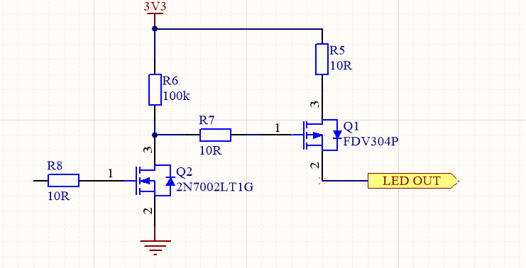
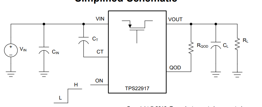
but now I have to save space for some additional circuit. So my idea is to use TPS22929 or similiar sot23 IC (handsoledring friendly) for switching  LED. Can I use it? LED is blinking, but not very fast - 10Hz-20Hz. Also my device is battery powered so I need something suitable for low power applications.

Can you recommend me something? Imax for new LED is 120mA.

Another candidate: TPS22860 (better for low power?)

Thank you,

Jan

  • Hi Jan,

    Welcome to E2E!

    For this application I would recommend using the TPS22917 which is one of our newer load switches that offers even lower current consumption than the TPS22860 and the TPS22929. The TPS22917 is also offered in the SOT23 package making it hand soldering friendly.

    One concern I may have with the application would be the duty cycle of the LED. Since the LED will be blinking, the device will have to turn on and off several times during normal LED operation. How long do you expect this LED to be operating?(e.g. all the time, half a day, 1 hour a day, etc..)

    Best regards,

    Andy Robles

  • Hello Andy,

    thank you for response!

    Hard to say this, but i think that no more than 300 cycles per day (1 cycle is 40 blinks - on->off). Do you have concerns about the powerswitch lifetime as it should be used for longer cycles (like switch display, do something and switch off)?.

    Thank you,

    Jan

  • Hello Andy,

    second question - do you see any problem if I will use this analog switch -TS5A3159-EP? I know that these should be used for analog switching, but it's current rating seems to be OK.

    I hope we will find best solution!

    Thank you,

    Jan

  • Hi Jan,

    To best know if the TS5A3159-EP would be a good solution you would need to start a new thread so that this question can go to the team that supports that device.

    In regards to the TPS22917, load switches are usually implemented to turn on or off a power rail and keep them on or off for longer periods of time. I am currently discussing with the team if the repetitive toggling of the device will impose a problem in the long run.

    I would like to ask a follow up question to understand the functionality of your current design. My assumption is that Q1 is used to pass power to the LED by using Q2 to control the gate of Q1. A question I have is on the diode connecting 3 and 2 on Q1 that seems to always be inputting 3.3V to the LED. Does this always output 3.3V to the LED in your design?

    Best regards,

    Andy Robles

  • Hello Andy,

    sorry I posted schematic with mistake - I was in hurry and I placed mirrored Q1. Schematic should look like this:

    So now it should work :) Q1 is used to pass power to the LED by using Q2 to control gate of Q1.

    Let me know what you team says.

    Thank you a stay safe during these times...

    Jan

  • Hi Jan,

    This would would be a typical application of the TPS22917 and the toggling of the load switch for 300 cycles or more would not be a problem for the TPS22917.

    For you application the CT pin can be left open to enable the fastest rise time. QOD can be connected directly to VOUT to allow a faster discharge although the fall time of the device is already very small relative to the duration of the off state during the blinking of the LED. VIN would be connected to the 3.3V rail and you would still need a resistor in series with the LED to limit the current to the LED. On pin is an active high switch controller and works with logic levels over 1V. The datasheet also has an application section further explaining configuration of the TPS22917.

    Let me know if you have any questions!

    Best regards,

    Andy Robles

  • Hello Andy,

    thank you and your team for support.

    So the "lifetime problem" you had concerns about is gone? Or what are the limits? Can 1000 cycles per day cause a problem? I did speak with customer and they have no statistics about usage. But they did ask for two versions of blinking:

    1) Previously described sequence - 20Hz for 3-5 seconds. 

    2) New one - just turn on LED for 3-5 seconds then turn off.

    It is used in safety product - before you open door, it blinks so the person on the other side is not hitted.The frequency of usage is dependant on door location. 

    So about my circuit:
    - QOD directly connected to VOUT

    - CT open

    - CIN - 1uF to have enough local energy for LED

    - CL - do I need to connect capactior in parallel with LED? 

    Thank you,

    Jan

  • Hi Jan,

    The concern was just something I thought could've been a problem, but the design team confirmed that the amount of the times the load switch is toggled a day is not a concern for the lifetime of the switch.

    For your circuit:

    CT: Can be connected to VIN via a capacitor to adjust rise time of the device. Can be left open for fastest rise time.

    QOD: Can be left open, connect to VOUT directly to use the internal resistance to discharge the output faster, or connect to VOUT via a resistor. You don't need an output capacitor to operate the TPS22917. If there is no output capacitor then there shouldn't be a need for the QOD pin to discharge anything, so you may leave it open.

    Let me know if you have any questions!

    Best regards,

    Andy Robles

  • Hi Andy,

    thank you, this helped me a lot!

    Stay safe,

    Jan