This thread has been locked.

If you have a related question, please click the "Ask a related question" button in the top right corner. The newly created question will be automatically linked to this question.

BQ24765EVM: ac power problem

Part Number: BQ24765EVM

Hello,

I am following the user manual for BQ 24765 on page 6. http://www.ti.com/lit/ug/sluu415a/sluu415a.pdf?ts=1587751942176

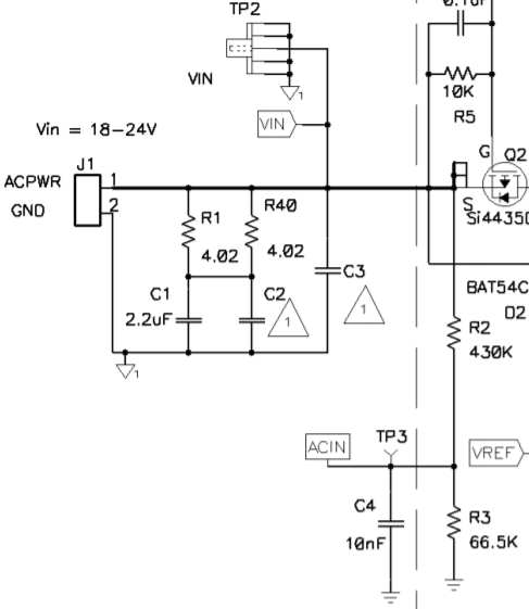
When I turn PS 1 on the diode D7 lights up. However, when I turn on PS 1 D5 does not turn on. Neither does any of the other diodes and the voltages are not correct. For instance, V(TP(ACIN)is -0.4V. The voltage reaches J1 on the circuit board but nothing else. Is this definitely related to the board and could this be a problem with the board? 

Thank You

  • Hi,

    Based on your observation that ACIN = -0.4 V, it definitely sounds like something is wrong with the hardware - perhaps a broken trace or an un-soldered pad.

    The ACIN voltage is set by a resistor divider from the adapter to ACIN to GND. The ACOK LED (D5) cannot turn on unless ACIN > 2.4 V.

    Can you please check to see whether the adapter voltage reaches TP2 (VIN)? If it does, then can you check the soldering for R2 and R3 to see why the ACIN voltage is incorrect?

    Best regards,

    Angelo

  • Hi there,

    Can you confirm that the board's jumper configuration is in the factory default state as per the table of section 1.4 in the EVM user guide? 

    The ACIN Test Point (TP3) is in the middle of a resistor divider directly between J1 PWR and GND, so it is a good starting point to debug.  Do you have a way to measure the input current at J1 and can you confirm that it is less than an amp (assuming you don't have a load applied at J10 connector and aren't charging.)  Do you measure the J1 voltage at TP2?

    If you have a multimeter that can measure resistance, can you remove the power from the board and measure the resistance from TP2 to TP3 and then from TP3 to TP1 (GND)?  The first measurement should be close to 430K and the second should be close to 66.5K. 

    If you can let me know what you measure at some of these points, we should be able to narrow down the source of the issue.  If you are measuring 20V at TP2 and -0.4V at TP3, then I don't see an explanation other than R2 is open, R3/C4 is shorted, or the IC is damaged (the ACIN pin should be high impedance.) 

    Regards,

    Steve 

  • Hello Angelo,

    Thanks for your help. TP2 is the same voltage as Vin. R2 and R3 seem to be the problem. After writing the previous sentences, I touched the multimeter probe a few more times to R2 and R3 and their voltages changed and the LEDs came on. Other than that I changed nothing. Maybe I wiped off some material on the resistors. I am confused but it works now. 

    Thank You,

    Brendan 

  • Hi Brendan,

    Great, thanks for the update! I'm glad the issue is resolved.

    I will close this thread for now, but feel free to let us know if you run into any other issues.

    Best regards,

    Angelo