This thread has been locked.

If you have a related question, please click the "Ask a related question" button in the top right corner. The newly created question will be automatically linked to this question.

BQ24765EVM: Charge Current and AC Current Regulation

Part Number: BQ24765EVM
Other Parts Discussed in Thread: BQ24765, BQ34110

Hello, 

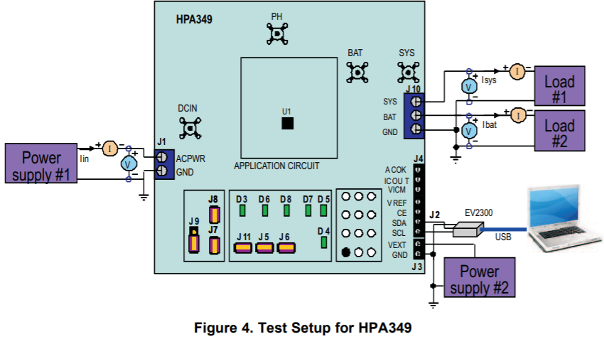
I have started up the board and proceeded through until page 7 of the manual (2.4.2.3) I am now on Charge Current and AC regulation. Do we need two loads for this section 2.4.3? That is, is there no battery in the setup? Previously I was using a power resistor for the load and a battery for the battery. 

Thank You

  • Hi,

    The purpose of Section 2.4.3 is to verify that the charger can charge the battery (Load #2) while simultaneously powering the system (Load #1). For example, Step 2.4.3.7 asks you to measure ISYS, IBAT, and IIN. Therefore, you will need both Load #1 and Load #2 for this. If you only use 1 load, then you will not have ISYS and IBAT at the same time.

    It's most convenient to use an e-load in CC mode for Load #1, and a bidirectional power supply (such as a Keithley sourcemeter) for Load #2. The e-load and the sourcemeter will display ISYS and IBAT, respectively. However, it's also okay to use a power resistor and a real battery instead.

    Best regards,

    Angelo

  • Thanks Angelo and sorry for my true noob questions! I chose to leave the battery and power resistor as is. I can now control current through the battery while power supply 1 still powers the load.


    For the evaluation software I have a few questions.


    1) What is the difference between the charge current and the input current?

    2) How does the user select the number of cells?

    3) Is the Charge Voltage the maximum voltage that the system will charge until? How is charging terminated? Only by manually inserting/removing J7?


    Also, I spoke online with a TI repesentative about what system to buy and asked for a system with State of Charge (SOC). Does this system have this and how does it measure SOC?


    Thank You,

    Brendan


  • Hi Brendan,

    No problem, I'm happy to help.

    1) The input current is the current from the adapter (Iin in Figure 4 below). The charge current is the current that flows into the battery (Ibat in Figure 4).

    2) Unlike some of our other chargers, the BQ24765 does not have a CELL pin to indicate the number of cells. Instead, the host MCU should set your desired charge voltage through SMBus control. Typically, Li-ion batteries are charged up to 4.2 V/cell.

    3) The ChargeVoltage() register sets the maximum voltage that the BQ24765 will charge the battery up to. There is no need to manually insert/remove J7. As the battery voltage rises and approaches the ChargeVoltage() register setting, the charge current will gradually taper down to zero.

    Any of the following conditions will disable charging. Since the BQ24765 is a host-controlled charger, the host MCU can disable charging through SMBus (for example, by setting the ChargeCurrent() register to zero).

    4) A battery's state of charge refers to its remaining capacity. Some of our other chargers (not the BQ24765) have an integrated ADC which allows the host to easily read the battery voltage. This can provide a rough idea of the remaining battery capacity, but you will need a battery gauge to accurately measure the SoC. Please see this page for an overview of TI's battery gauges:

    http://www.ti.com/power-management/battery-management/fuel-gauges/overview.html

    Lastly, can you please provide some more information about your application? What is the end equipment, and what are the battery charger requirements? I'm happy to continue answering your specific questions, but knowing more about the big picture could help me point you in the right direction for your application.

    Best regards,

    Angelo

  • Hi Angelo,


    I work for a special purpose battery company. We make prototypes of all types of battery’s for different applications. We work with lithium metal, graphite and silicon lithium anodes with practically every cathode material. We specialize in small scale battery manufacturing and have little experience with battery management systems. We would like to develop this ability.

    We are using TENERGY Ni-MH rechargeable D-cells. We are currently attempting it with 2 cells in series which is about 2.5 V. We need state of charge management while the batteries are charging and discharging.


    Thank You,

    Brendan

  • Hi Brendan,

    Okay, thanks for the information.

    You will need a gauge to accurately measure the battery's SoC. Also, your host MCU should control charge termination, which is handled differently for Li-ion vs. NiMH batteries. Please refer to this related E2E thread for more details:

    https://e2e.ti.com/support/power-management/f/196/t/744478

    Best regards,

    Angelo

  • Hi Angelo, 


    So basically I would use the BQ24765 EVM in conjunction with a gas gauge. My understanding is that the BQ24765 EVM can handle charge termination because it stops charging upon a voltage threshold. For the gas gauge I have filtered based on NiMH chemistry. If I used multiple cells than my only option is the bq34110. ( https://www.ti.com/tool/BQ34110EVM-796 ) I could also use https://www.ti.com/tool/BQ27220EVM-744 for a single cell.


    Thank You,

    Brendan

  • Hi Brendan,

    It sounds like you're on the right track. Please create a new E2E thread with one of your gauges in the title so that TI's gauge experts can provide more detailed suggestions.

    Best regards,

    Angelo