This thread has been locked.

If you have a related question, please click the "Ask a related question" button in the top right corner. The newly created question will be automatically linked to this question.

LM3150-250EVAL: LM-3150 , new eval board with big Jitter

Part Number: LM3150-250EVAL
Other Parts Discussed in Thread: LM3150, , LM25145, LM73605

We got an LM3150 Eval250 board.
We started our test with Vin 24V and 1-5A load.

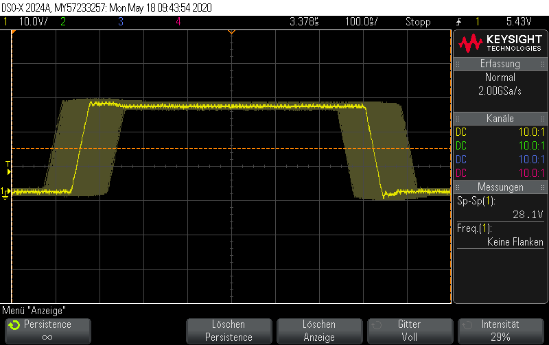
We see in the original Eval Board configuration a very large jitter in the rising and falling edges of the switch node. Up to 400ns of jitter.

That surprises me a lot, especially since the design is optimal. So noise on FB could not be.

I put the ripple injection circuit on the board
The jitter has been reduced . However, I can't get him away completely.
I still have 100ns jitter in the SW node.
I've also tried a few values.

If everything else works, is a jitter of 100ns acceptable?

Regards Rainer

  • Hello Rainer,

    I would highly recommend referring to the below-mentioned E2E thread, this thread has already addressed a similar issue.

    Please have a look into this, if it doesn't resolve your problem, we can definitely have more discussion on this.

    https://e2e.ti.com/support/power-management/f/196/p/754261/2807687#2807687?jktype=e2e

    Hope this helps!

    Best Regards,

    Ankit Gupta

    Application Engineer

  • Hello Ankit Gupta,

    I read the thread and this is exaclty what Iám trying.

    I was wondering that the Demo board has such a Jitter.

    As I told you, I try the ripple injection circuit with several configurations, but

    I come never under a jitter of 100nsec.

    So the question again, is a jitter of 100ns aceptable  or ok ?

    Best Regards

    Rainer

  • Hi Rainer,

    Depending on the switching frequency, 100ns may be acceptable. What are the component values for the ripple injection circuit? In terms of PCB layout, please ensure the coupling cap is located close to the FB pin and the FB trace is as short as possible.

    Regards,

    Tim 

  • Dear Tim,

    regarding the PCB Layout, it would be on the LM3150-250EVAL board.

    For Ripple inj. , I take the values from Web DEsigner, see attachend.

    But with this values  the Jitter becomes alway big.

    I tried to reduce the Rr down to 680k Ohm. Then I have the best result with the Jitter of r.a. 100ns.

    Do you have better vaules for trying ?

    Attachend I have a screenshoot of the Switch Node.

    You see in the  persistence mode the wide of the Jitter.

    Best Regards

    Rainer

  • Dear Tim, another question.

    If i have no load the frq on switch node is stable ( exception to the described jitter).

    If i set a load of for example 5A the FRQ on switch node increases by about 16kHz.

    Meanwhile I Set the Ron to 150k, which should be 300kHz. In real there was 334kHz.

    So if i Have no load there was 334 kHz, with load 5A there was 350kHz.

    Is this normal for the LM3150 and the evalboard ?

    Note: If had changed the L to 6,8 µH on Evalboard and also the set to 5V. I only test at the moment with 24V DC input.

    Best Regards

    Rainer

  • Meanwhile I test further.

    If I reduce the Rr down to 330k, then the Jitter on SW node was very small.

    But I see something else, while reduce the Rr , the FRW is going up.

    I See with Ron 150k and no Ripple Injection r.a. 300kHz.

    I see with Ron 150k and Ripple Injection Rr 680kOhm = r.a. 330kHz

    I see with Ron 150k and Ripple Injection Rr 330kOhm = r.a 370 kHz.

    If I See that I Have the lowest Jitter with 330k Ohm , I Will ask, if this is ok to reduce the value in such a way ?

    But why is the frequency is going up ?

    Best Regards

    Rainer

  • I see that if I Reduce Rr the the FRQ is going , and also the Output value.

    So reducing the Rr is not the solution.

    So I was near begiing. Without Ripple Injection a have a big Jitter in the Switch Node of the Demoboard.

    Trying with Ripple Injection reduce the Jitter but increase the FRQ and the ouput Voltage.

    What can you recommend in that Case ?

    Best Regards

    Rainer

  • Hi Again, I Found a hint in the Datashet about this effect :

    Notethatthiswillcausea slightchangein thenominaloutputvoltageduetothefactthatthebottom,nottheaverageoftherippletriangleis beingregulated.If desired,thefeedbackdividerratiocanbeadjustedslightlytocompensate.

    But in my Case the Voltage is going up to 5,6V insteadt of 5V.

    The Summary actually is.

    The Demoboard without ripple injection has a big jitter in SW node.

    The Demoboard with ripple injection and values which make less jitter , has a bigger Output Voltage and FRQ.

    So, what can I do. ?

    Please advise.

    Best Regards

    Rainer

  • Hi Rainer,

    Please consult the LM3150 quickstart calculator for assistance with component selection: https://www.ti.com/tool/LM315XQUICK-CALC

    Please note the inject ripple amplitude at FB as this affects stability and jitter performance as well as the output voltage setpoint (given that regulation occurs at the valley of the ripple waveform for a COT architecture).

    Regards,

    Tim

  • Hi Rainer,

    Here are some additional notes:


    1. Use higher resistance FETs. The ripple injected internally is based upon the ripple across the low-side FET. Use a FET with Rdson >= 10mOhms increases the in-phase ripple injected.  Higher is better for jitter.

    2. Higher Cout ESR, or 2b) add ripple injection onto feedback. 

    3. Sometimes a Cff is enough.  It’s all about how much in-phase ripple reaches the FB pin.


    Another controller option here (voltage-mode control with excellent stability performance) is the LM25145. Alternatively, consider a converter such as the LM73605.


    Regards,

    Tim