This thread has been locked.

If you have a related question, please click the "Ask a related question" button in the top right corner. The newly created question will be automatically linked to this question.

LMZ21701: Average model or Rvrm and Lvrm values requirements for PI analysis

Part Number: LMZ21701
Other Parts Discussed in Thread: TPS62130, TINA-TI

Hi TI team,

I'm using LMZ21701 in my design. For AC impedance decoupling analysis, ALL Power Integrity (PI) simulation softwares (ADS PiPro/Hyperlynx PI/ Power SI) are asking for the following two parameter values:

R_vrm = low output impedance value during active regulation

L_vrm  = active inductance due to the feedback loop of the regulator which occurs for the frequencies beyond the active regulation range of the regulator.

These values can be extracted from a steady state model which is not provided in the website.

Hence, please provide these two parameter values so that I can feed these values in PI tool and proceed further.

If TI doesn't have these values, how does TI expect the regulator to be accurately modeled in all of PI simulators? Not only that, without such VRM model, the whole PDN impedance design becomes questionable. Hence, these two parameters hold very important place in PDN decoupling analysis.

Thanks,
Binayak

  • Hi Binayak,

    We do not often have an average model for devices using DCS control which is a COT-like topology.

    There is an average model for a similar device TPS62130, which you possibly use to get what you are looking for. You can use a 2.2uH to emulate what is used in the module.

    https://www.ti.com/product/TPS62130#design-development

    I hope this helps,
    Kris

  • Hi Kris:

    Thanks for your reply.

    Here are the follow up questions to get a better clarity of your answer :

    (1) Is there a known regulator IC inside the LMZ21701 module or is it a brand new regulator IC?

    (2) If it's a new regulator, is TPS62130 closest to it?

    (3) You have mentioned about the 2.2uH inductor in the EVM of TPS62130? Does this mean that the inductor mounted inside LMZ21701 is also 2.2uH?

    The active inductance (L_vrm) that I need is not the value of external inductor. It is the inductance value used to model the rise in output impedance with frequency as the regulator starts to lose it regulation ability due to the limitation of the control feedback loop.
     

    Best Regards,
    Binayak

  • Yes, TPS62130 should be close.

    The LMZ21701 datasheet has a functional block diagram on p.9 which mentions that the internal inductor is 2.2uH.

  • Hi Kris:

    Since I wanted the output impedance curve, I downloaded the TINA-TI reference design of TPS62130 and tried finding the output impedance.

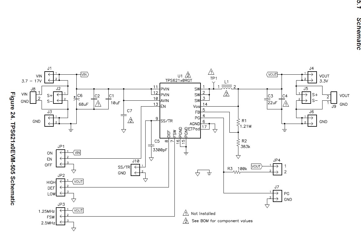
    The schematic of the EVM is as shown:

    To obtain the output impedance, I modified the TINA-TI average reference design by removing the voltage generator at the load, including a current source and changing the load resistor to a very large value as a current source impedance, and finally adding an ohm-meter. The modified setup is as shown:

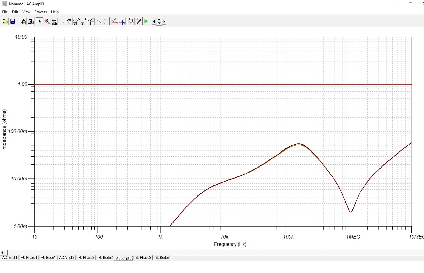
    I then simulated the ac transfer transfer characteristics as shown:

    The flat line is the gain which I am ignoring. The ohmmeter curve looks similar to a typical output impedance of a VRM (with a bulk cap). Is the output impedance curve correct?

    Best Regards,

    Binayak

  • Hi Binayak,

    The curve looks reasonable but I am unsure on the need for that current source if you are using the ohmmeter. Does the result change if you remove it?

    Regards,
    Kris

  • Hi Kris:

    You are correct. The current source is not required when using the ohmmeter. It gives the same result if I remove it.

    So I can go with the supposition that the output impedance curve for LMZ21701 will follow similar values (though not exact). Right?

    Thanks,

    Binayak

  • Binayak, yes I would think so, but there is one more thing to mention - the average model file mentions that it is only valid in CCM operation.

    At light loads, the LMZ21701 (and TPS62130) has a power-save mode PSM in which the switching frequency decreases linearly with the load current to increase light-load efficiency. The device automatically switches to PSM mode below about ~200-300mA based on the efficiency curves on the LMZ21701 datasheet first page.