This thread has been locked.

If you have a related question, please click the "Ask a related question" button in the top right corner. The newly created question will be automatically linked to this question.

UCC2818A-Q1: MOSFET selection and Power loss with given gate resistance

Part Number: UCC2818A-Q1
Other Parts Discussed in Thread: UCC2818

HI TI,,

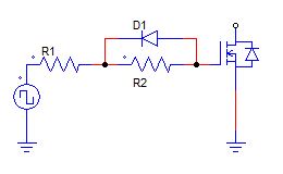
Please help me to get the correct gate resistor and mosfet for the UCC2818A-q1 because as given picture you are using 20E resistance which is source of switching loss .my spec is AC 85 to 265 and out 390V 750W (1.92Amp). so if i calculate the power loss I^2x R loss with a mosfet the conduction loss is less (0.44W) but while calculate the switching loss with 100Khz switch frequency it is 26W which is very high with 20E resistance.

Can you please let me know the gate resistance value which i should use.

i am using below formula to calculate the switching loss : MOSFET part Num : STWA30N65DM6AG

i peak :13amp

Vds: 390V

Fw :100Khz

Tch: 50n

  • Hi ti,

    i am in mid of calculation please share your view ASAP.

    Thanks,

    Dinesh

  • Hi Ti,

    i am waiting for your reply . if you are able to support please let me know else i need to find some other resource.

    i am in mid of calculation.

    Thanks,

    DInesh Gread

  • Hi Dinesh

    It's difficult to predict what the best gate resistor value should be - if you use a very low value then you get faster switching but greater EMI because of the higher dv/dt rates. If you use a higher value then the switching becomes slower but the switching losses increase.

    My advice would be to use a slightly more complex network than that shown in the data sheet. The turn-on resistance is R1+R2, the turn-off resistance is R1. D1 is a fast signal diode - rated for the peak current in R1 during turn-off.

    Use 1206 size resistors unless you can get peak pulse current ratings from the manufacturer.

    For an initial development - Try R1 = 2.2R and R2 = 1R

    You will have to experiment on hardware to get the best balance between switching speed and EMI.

    You may wish to contact the MOSFET manufacturer to discuss this because they will have much better insight into the switching behaviour of their devices than TI has. Finally, you may wish to consider using a separate MOSFET gate driver - this can be useful because the gate driver can be placed directly at the MOSFET whereas the controller may have to be placed a little distance away to allow routing for feedback and other signals.

    Regards

    Colin

  • HI Colin,

    Thanks for the reply.

    i am consider below attached circuit . will it be okay for 650W PFC application.

  • Hi Dinesh

    It should be ok - we used it on a 900W PFC design - http://www.ti.com/tool/TIDA-00443

    The designer added an option to use either an external driver or the internal driver of the controller - so it's a little more complicated than the circuit above.

    Regards

    Colin

  • Hi Colin,

    i am using ucc2818a-Q1 , will be there any issue if i directly drive the MOSFET using PFC controller.

    any pros and cons please share your thoughts.

    Regards,

    Dinsh

  • Hi Dinesh,

    In CCM PFC the gate drive speed is quite important so been able to turn on and off the Mosfet quickly to minimise switching losses.

    I suggest adding a totem pole NPN/PNP driver to the design with an option to not fit the transistors and let the UCC2818 dierctly drive the main fet.

    I have see high efficiency CCM at 900W use the controller to directly drive the PFC mosfet.

    Regards

    Peter