This thread has been locked.

If you have a related question, please click the "Ask a related question" button in the top right corner. The newly created question will be automatically linked to this question.

LM3410: LM3410

Part Number: LM3410

Dear Team,

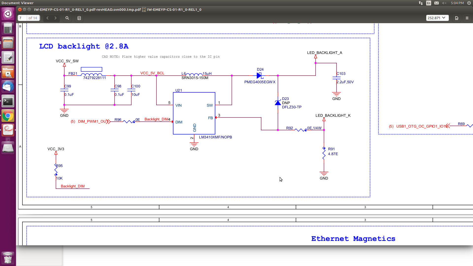
I am using LM3410XMF/NOPB part in my design as power source for LCD backlight.

The required output voltage is Vout = 22.4V and Iout = 80mA.

But when I turned ON then I am observing 4.98V at the output, may I get some suggestion for resolving this issue.

I am attaching the schematic pdf for your reference. 

With regards,

Jayashree.

  • Hello Jayashree,

    A boost converter will feed the input to the output through D24 so even when it is not switching there will be output voltage when there is input voltage.

    Have you looked at the SW node, fb node?

    Note, if there is no over voltage protection the device will be damaged with an open load or a load that allows the SW node to exceed abs max which is 26.5V.

    Best Regards,

  • Hi,

    Thanks for the reply.

    Could you suggest me is there any mistake in circuit, because the circuit is designed to get 22.4V at the output.

    Guide me in resolving this issue.

    With regards,

    Jayashree.

  • Hello Jayashree,

    I don't see anything wrong with the schematic.  I don't know what you are doing with DIM and if the components such as the inductor are correct for the design.  If you don't connect a load that limits the output voltage you will, most likely, damage the part.  It has to have a path for current otherwise it will boost until the MOSFET avalanches.

    Have you looked at the SW node, fb node and other pins to see if it is trying to operate?

    If you have the LED load you can try running 80 mA through it and measure the voltage across it to make sure it isn't too high.  You can also try a lower voltage LED stack to get it running as well though it has to be higher than the input voltage because this is a boost converter.

    Best Regards,

  • Hi Team,

    Sorry for late reply.

    The DIM is connected to VCC_3V3 through a 10K resistor, and also connected to processor through a 0E resistor. 

    If everything would work as expected then I would give a PWM signal from processor to DIM pin to control the brightness of the LCD.

    I had measured voltage at other pins and observed that at SW node = 4.98V, FB node = 189.7mV, VIN = 4.98V, DIM pin = 3.3V, GND pin = 0V. 

    The point that you mentioned is to connect a LED across LED_k and LED_A and measure the voltage, is that you mean to say? 

    I am attaching the details of requirement for which I had designed this circuit. Please have a quick look and let me know if I am missing out something.LCD Backlight circuit.docx

  • Hello Jayashree,

    If the IC is okay and FB node is at 189.7 mV it would be in regulation.  Is there 189.7 mV across R91?  If so there must be current going through it and most likely the load connected to it.  Also check to see if R91 is actually 4.87 ohms and not something else like 4.87 Kohm.

    Do you know if the LM3410 is okay?

    Have you verified that D24 is installed correct, R92 is zero ohms and on the board, the leds are connected correct?

    Have you externally powered up the leds to see what the voltage across them is?  Yes, measuring from Anode to cathode.

    Can DIM be applied before the LM3410 has power?

    This circuit is fairly simple and just works when everything is within operating range.

    Best Regards,