This thread has been locked.

If you have a related question, please click the "Ask a related question" button in the top right corner. The newly created question will be automatically linked to this question.

BQ25886: Short Circuit on The Charger Circuit

Part Number: BQ25886

Hello,

I designed a USB controlled battery charger circuit with BQ25886RGER. When I connect 7.4V from power supply to cell connection nodes which is H2 in my design, I read on the power supply as a short circuit. Then, I removed this circuit from the PCB, the short circuit was solved. The output of this charger circuit, "Power from battery", feeds to 5V and 3.3V voltage regulators. My plan during designing of the circuit, when I connect a 7.4V, the charge circuit will be bypassed and conduct the 7.4V to the regulators directly. After removing the circuit, I soldered a jumping cable between H2 nodes to the regulator inputs, but the remaining circuit was not worked either. Do you have any suggestions to solve the problem?

Thank you,


  • Dear Alpaslan,

    For my understanding, you are trying to use a power supply in place of a battery to source current to the system load? Can you please capture some waveforms of VBUS, BAT, SYS and SW? You should be able to enter supplement mode even without an adapter, but I need to see waveforms to diagnose this issue.

    In addition, the rail for the TS is intended for the 4.8 V REGN voltage. The TS fault decision is made relative to the voltage on this pin.

    Thanks,

    Mike Emanuel

    Please click "This resolved my issue" button if this post answers your question.

  • Hi Mike,

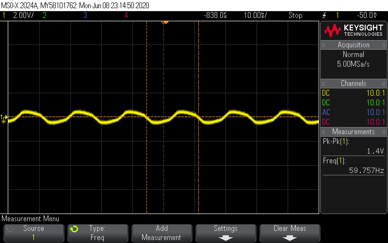
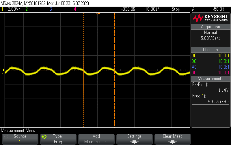
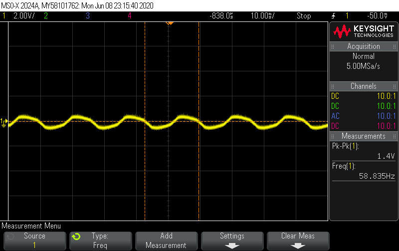
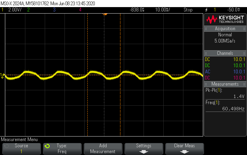
    Yes, it is true. I have attached signal measurements from four pins. All of them are the same even TS.

    BAT:

    --------------

    SW:

    -------------

    SYS:

    ----------

    VBUS:

  • Dear Alpaslan,

    Can you please measure the VBUS line with a multimeter? It doesn't even seem like you have a valid input.

    Thanks,

    Mike Emanuel

    Please click "This resolved my issue" button if this post answers your question.

  • Hi Mike,

    Yes, exactly. Because whenever I connect power input to the PCB, it goes short circuit and power supply drops from 7.4V to 2.2V. Do you think the circuit is okay, and the problem is related with other part of the PCB.

    Thank you,

  • Dear Alpaslan,

    Can you please send a layout? In addition, you said that when you remove the power supply from the battery connection the problem is solved. Can you capture the waveforms above, but when the circuit is working? Can you double check the attachment of the power supply of 7.4 V as this seems to be the issue?

    Thanks,

    Mike Emanuel

    Please click "This resolved my issue" button if this post answers your question.

  • Ok, I attached the layout. But it may be hard to follow up on the layout. I connected the 7.4V battery instead of power supply and 5V 1A power to VBUS. I measured with multimeter and VBUS has 5V.

  • Dear Alpaslan,

    I am confused, does the issue appear with a 7.4 V battery or with a 7.4 V power supply connection on the BAT pin? If you are trying to tie a power supply to the BAT pin that will not work. The charger will try to input current into your power supply when your power supply is only capable of outputting current.

    Thanks,

    Mike Emanuel

    Please click "This resolved my issue" button if this post answers your question.

  • Now I double tested for two cases. I soldered only battery charger and regulator circuits on my PCB, then in the first case, I connected a power supply to the BAT pin with 7.4V. There is no short circuit, and regulators work well. I guess the short circuit was related to other parts of the PCB. 

    In the second case, I connected 7.4V batteries, which are empty, to the BAT pin. Then, I connect 5V 1A power to VBUS with GND connection. So, the LED indicators were not responded and blinked. I measured that VBUS has 5V. So, the IBUS current is not enough?  

  • Dear Alpaslan,

    Glad to see the short is resolved!

    So are the STAT and /PG LEDs blinking or off? What is happening to the battery in this case? Is there battery current? If you attached depleted batteries below V_BAT_SHORT, you may be in trickle charge.

    Thanks,

    Mike Emanuel

    Please click "This resolved my issue" button if this post answers your question.

  • STAT AND /PG LEDs are off. When I connected 5V power and measured battery voltage, it was not changed. Should I wait for a long time? I measured like 4uA as the battery current. You mean the battery has at least some voltage? What is the V_BAT_SHORT value? Does trickle charge mean that really slow charge process?

  • Dear Alpaslan,

    What is the waveform of VBUS, BAT, SW, and SYS now that you have your circuit partly working? The /PG LED being off indicates a bad input source. The STAT pin being off indicates charging complete or charge disabled. What is your battery voltage that you attach? V_BAT_SHORT is 4.4 V.

    Thanks,

    Mike Emanuel

    Please click "This resolved my issue" button if this post answers your question.

  • VBUS is 5V but it has small peaks appearing periodically. BAT and SW are 0V and noisy. Battery voltage what I have attached is 0V. 

  • Alpaslan,

    Can you please upload the waveforms? If your battery voltage is 0 V you will definitely be in trickle charge. What happens if you attach a 5 V battery?

    Thanks,

    Mike Emanuel

    Please click "This resolved my issue" button if this post answers your question.

  • Hi Mike,

    I recognized that when I connect 5mV charged battery to BAT connector and plug in 5V/1A power adapter, the 5mV was decreased to 3mV. Why the discharging happens?

    Thank you

  • Alpaslan,

    What happens when you charge with a normal battery voltage? If your battery is at 5 mV, I would worry about the health of the battery for the future. What battery range do you intend to charge at?

    Thanks,

    Mike Emanuel

    Please click "This resolved my issue" button if this post answers your question.

  • The full battery voltage is 7.4V. I want to initiate the charging when the battery is lower than 3.3V. For testing, I have almost empty batteries. So I connected them to BAT connector for charging and 5V/1A power adapter to VBUS, but it wasn't charged even small voltage in the batteries are discharging.

  • Alpaslan,

    It seems based upon previous posts we are still experiencing a bad input because your /PG led is off. If you do not have a valid input you cannot charge the battery. Can you please probe specifically the VBUS pin on the integrated circuit?

    As a separate note, I am worried about your layout. It seems as if you have no pours for the power traces. Instead, you have thin narrow traces connecting everything which imposes higher resistance. For example, the VBUS pin does this. If the resistance is high enough, the chip may not be receiving the right voltage on the VBUS pin in order to function correctly. If you apply 5V to your PCB, you need to measure the actual pin voltage.

    In addition, we do not recommend discharging lithium ion batteries to 5 mV. You need to have a protector on the battery to prevent over discharge in order to mitigate cell stress and cell lifetime issues.

    Thanks,

    Mike Emanuel

    Please click "This resolved my issue" button if this post answers your question.

  • Alpaslan,

    Do you have any updates?

    Thanks,

    Mike Emanuel

    Please click "This resolved my issue" button if this post answers your question.

  • Hi Mike,

    I will update my PCB design. I will redesign based on your recommendations. Before starting, what is your battery protector IC recommendation with BQ25886? 

    Thank you,

  • I would recommend looking for a protector on the Battery Protector Product Page, posted below. Once you find one that meets your requirements, you can start a thread about that specific part.

    https://www.ti.com/power-management/battery-management/protectors/overview.html

    Also, as this will be a new PCB design, can you make a new thread while keeping the schematic?

    Thanks,

    Mike Emanuel

    Please click "This resolved my issue" button if this post answers your question.