This thread has been locked.

If you have a related question, please click the "Ask a related question" button in the top right corner. The newly created question will be automatically linked to this question.

TPS62050: Power On Issue

Part Number: TPS62050

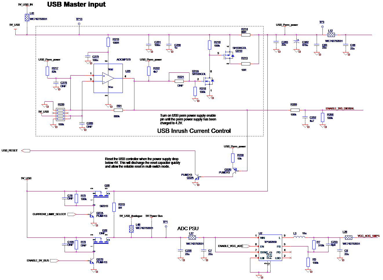
We have a power-on issue to use the power management IC, TPS62050. There is the inrush current control in the design, it will limit the current drawn by the IC to be less than 12mA to be able to complete the power-on procedure properly. On the specification, the max quiescent current is less than 30uA, but during the power-on procedure the current drawn by TPS62050 will reach 20mA sometimes when the EN pin keep 0V and the VIN pin’s power voltage increase gradually. It normally happens at about 2.3V when the device is turned on after switch off for long period (the ambient temperature is still 20 °C). We are not sure for what reason the high quiescent current has been triggered, but some of our device failed to power on for this reason. Once it passed the certain level, the IC works fine.

  • Martin,

    The quiescent current specification is for power save mode with SYNC = LOW.  You have SYNC pulled up to Vin so you are operating in PWM mode.  Even with SYNC pulse dow, you may encounter peak currents higher than 12 mA during the high side on time.  With EN = LOW, the input current should be very low, about 1.5 uA.  Of course this is not a "power on" condition as the TPS62050 is disabled until EN is high.  Can you try it with SYNC tied to GND?

  • Hi John,

    Thanks for the suggestion.

    In the specification, there is requirement to set SYNC to low on the operation quiescent current, but the quiescent  should be less than 5uA when EN set to low. We have several thousands of the products on the market, and there are several reports on this issue, and it happens occasionally. We always set SYNC pin to high and fix on the PWM mode to reduce the noise interference which might couple to the ground.

    Do you have any other solutions to solve this issue?

    Regards,

    Martin


  • Martin,

    Can you provide a detailed description of your power on sequence and point out exactly when you see larger than normal current?  How often does it occur?

  • Hi John,

    When the power 5V_USB_IN connects to the 5V power supply, it will be charged USB_Power_Perm and 5V_Power_Bus through the resistor R214 (68R). On the failure case, when the power supply reaches the certain voltage level, about 2.3V, the current drawn by the TPS62050 is about 20mA and it will stop the USB_Power_Perm to reach 4.2V which is the threshold set by the comparator ADCMP370(U29). The output of the comparator will keep low, and the device fails to start.

    We have found several of our devices have power-on issue on several thousands of products.


    Thanks,


    Martin

  • Martin,

    While the voltage is rising to 2.3 V, is EN high or low?

  • Hi John,

    The EN is low while the voltage is rising to 2.3V. On the power-on procedure, the EN keeps near 0V which I have checked  on the power-on waveform. We have done some investigation, the different TPS62050 chip, the voltage level will be slight different. In the beginning, we consider that the TPS62050 have been damaged, but it works fine once it pass this voltage. This failure normally happens when the device power on after it have been switched off several hours.

    Thanks,


    Martin

  • Martin,

    Yes, but is EN still low when you observe the issue?  Let me know.

  • Hi John,

    Yes. The EN is low when I observe the issue.

    Martin

  • Martin,

    It is extremely unlikely that TPS62050 can draw 20 mA when EN is low.  We are going to check it in the lab.  It is an easy test.  If we have available hardware, I should have an answer for you this week.  If we have to order it, then it may be several days or more due to the present conditions.

  • Hi John,

    I have spent quite lot time to confirm it for we thought that it were some design issues which caused some faults on the TPS62050 in the beginning, but the circuit design looks fine after we did more test. It looks the slower charging slew rate is more easy to trigger the high current on the TPS62050. 

    Regards,

    Martin

  • martin,

    The state of the SYNC pin does not matter when EN is low.  We find it unlikely that the TPS62050 can draw even 0.1 mA of current when EN is low, but we are going to check it.  It is likely that something else is drawing current, but we will let you know what we find.

  • Thanks John,

    I have measured the total USB current and removed the L27 to fit the current meter to measure the current drawn by the TPS62050 when the EN is low.

    I am looking forward to hearing to hearing from you.

    Regards,

    martin

  • Martin,

    We measured an EVM.  Current never exceeded 1 uA.  I think if you are seeing 20 mA, then the IC may be damaged.

  • martin,

    Are you planning to submit a failing device for failure analysis?

  • Morning John,

    Thanks for the feedback. On this design, there are three TPS62050 chips to connect the USB_Perm_Power,and I have tested that two other TPS62050 ICs also show this issue when I  increased the R215 to 470R and dropped the USB input voltage to 3.8V.  The USB_Perm_Power can only be charged to 2.3V, and the other TPS62050 have drawn about 20mA the EN pin the IC kept low. I wonder if the batch of TPS62050 have the same issue. We have used this design in quite lots of the products, it hasn't shown this issue before.

    How could you verify if the IC was damaged? It works fine once passed the power on procedure.

    Regards,

    Martin

  • Martin,

    it is possible there is some defect.  I suggest you submit 2-3 of the failing devices for failure analysis.  Your local TI field support should be able to assist you with it.

  • HI John,

    Thanks for the help.

    I have only one device for the test at moment, we might send one to you for the investigation once we receive more devices from the customers. If they were from the same batch of an order, it might be the faults on these components.

    Best regards,

    Martin