This thread has been locked.

If you have a related question, please click the "Ask a related question" button in the top right corner. The newly created question will be automatically linked to this question.

LM27762: constant +5V and -5V

Part Number: LM27762
Other Parts Discussed in Thread: TL072,

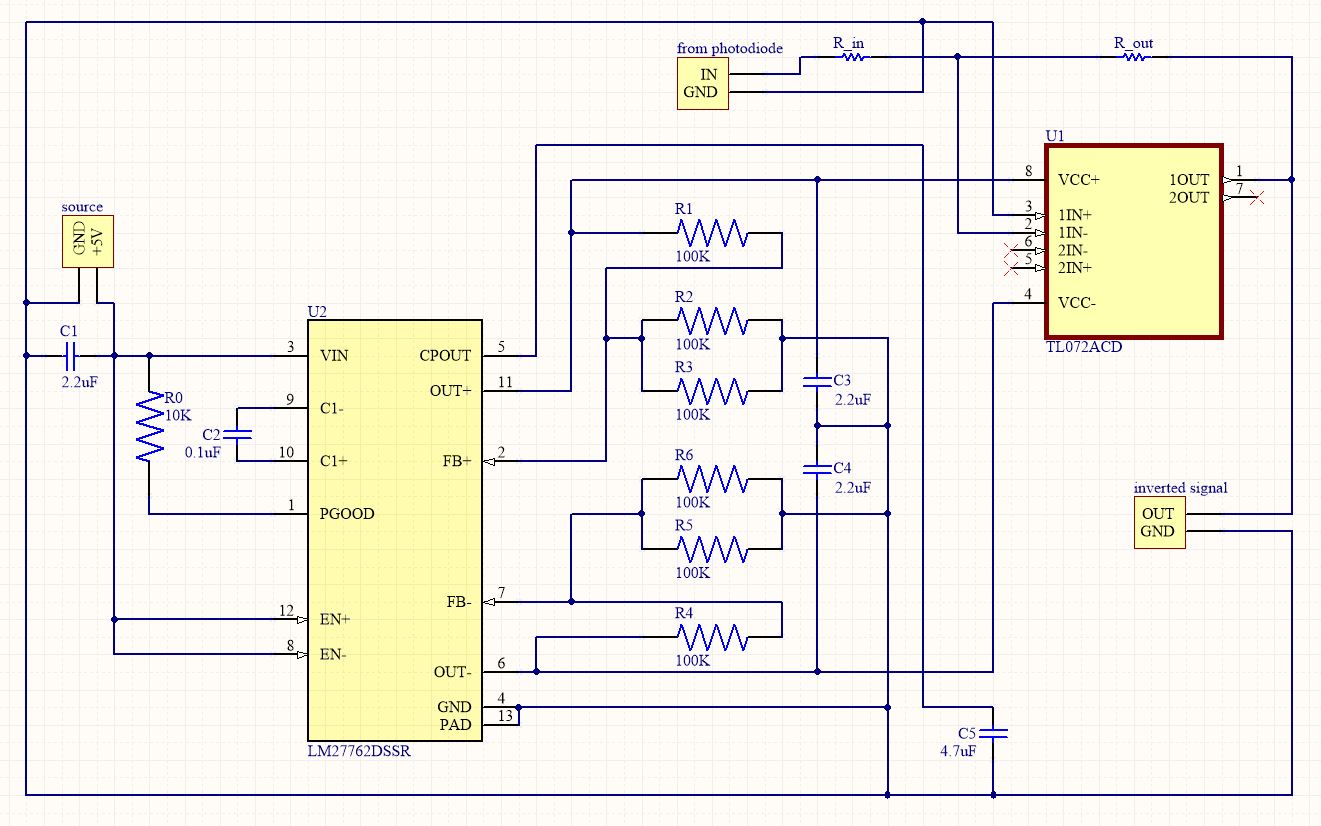
Hi, I need to use TL072 IC as an inverting amplifier, for that, I need to use LM27762 to provide +5V and -5V.

Will LM27762 be able to provide constant +5V and -5V? or do I need to put some external resistors and capacitors, as shown in the application part of LM28662 IC datasheet?

  • Hi Apurv,

    The external resistors and capacitors are vital for the operation of the LM27762.

    The value of the resistors can be chosen by following Sections 8.2.2.2 and 8.2.2.4 of the datasheet.

    The external capacitors should be chosen by following all the Sub-Sections of Section 8.2.2.5.

    The layout guidelines for connecting the external components to the LM27762 are given on page 17 and 18 of the datasheet.

    Like my teammate mentioned in your original question LM27762: LM27762 as constant -5V source. The LM27762 is able to simultaneously provide a +5V and a -5V output.

    Regards,

    Davor

  • Hi, Davor, thank you for the clarification.

    As I have mentioned earlier, I am using LM27762 to provide input voltage to TL072, which I am using as an inverting amplifier. I have made a circuit that should provide +3.6V and -3.6V to TL072 IC.

    I am attaching the PDF, can you cross-check? I have printed the PCB and soldered the components, checked each connection with a multimeter as well, but I am getting output voltage from LM27762 IC as 0.0V only.

    Thank you for your help.

    Regards,
    Apurv

    1423.schematic.pdf

  • Hi Apurv,

    Could you send a clearer schematic, because I do not understand which is the input to the converter. I would prefer that the ground symbol (GND) is used so that it is clearer where the GND is. Also what are the source, input and output headers? 

    Are the EN+ and EN- pins connected to anything? Because in order to have a regulating output, the related EN pin has to be set to HIGH.

    Regards,

    Davor

  •  Here's the updated schematic.

  • Hi Apruv,

    I can't find any problems with the schematic. 

    I have a few more questions and suggestions:

    1. What power source are you using at the input (what is the current limit, voltage rise time)? Perhaps you could also send me measurements of the voltage at the EN pin and VIN.

    2. I suggest disconnecting the load from the LM27762 to see if the converter is able to regulate the voltage in a no-load condition. 

    If you can please send the layout for review as well.

    Regards,

    Davor

  • Hi, Davor!

    Thank you for your quick reply.

    Previously, the EN pins were not connected, I believe that is the problem.

    The voltage at VIN and EN is around 4.86V.

    Thank you for your help.

    Regards,
    Apurv