Because of the holidays, TI E2E™ design support forum responses will be delayed from Dec. 25 through Jan. 2. Thank you for your patience.

This thread has been locked.

If you have a related question, please click the "Ask a related question" button in the top right corner. The newly created question will be automatically linked to this question.

BQ77905: Implementing Load Detect using High-Side Protection

Part Number: BQ77905

Hi:

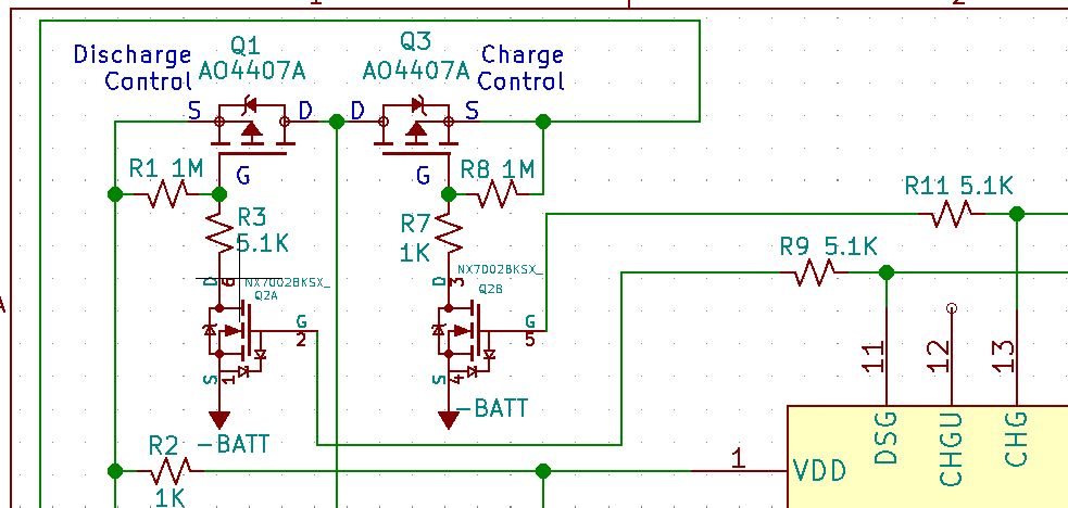
I have designed a basic schematic to use the BQ77905 parts in a high-side battery protection setup.  Load Detection is only desired for use with Current Faults, I do not see an obvious method for LD implementation at this point.  Below is the schematic for the high-side FETs, the LD pin is simply tied to -PACK via a 453K resistor.  Suggestions would be appreciated!

Thanks- Tom


  • Hi Tom,

    You are correct, to enable load detect you simply need to tie the LD pin to PACK-. However, we recommend a resistor between the values of 160kOhm and 375kOhm.

  • Hi Shawn:

    So the LD function will work properly with High-Side protection just by using a lower value LD resistor, from 160k Ohm to 375k Ohm ?

    Tom

  • Hi Tom,

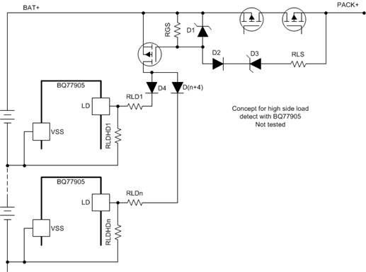
    Apologies, after thinking about it some more I do see the faults. I found this untested, hypothetical configuration of how it would work. 

  • Hi Shawn:

    I appreciate the possible circuit remedy, I will investigate further.

    Tom

  • Hi Shawn:

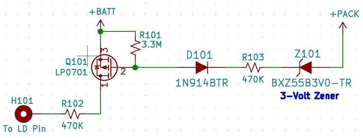
    I`ve experimented with the concept circuit you displayed above.  It seems to work with the components shown below.  Please review what I have and let me know if you see any problems with my selections... I am open to all suggestions. Thanks- Tom

    Here are the readings on the operational circuit:


    No Fault Over Current Fault
    to LD Pin 0.015V 3.85V
    Q101 - S - pin 1 (Batt+) 11.81V 11.92V
    Q101 - G - pin 2 8.38V 1.68V
    Q101 - D - pin 3 0.01V 11.91V
    Diode D101 at 100K R103 11.19V 1.36V
    100K R103 at Zener Z101 11.28V 1.07V
    PACK+ 11.80V 0.00V


  • Hi Tom,

    Per the datasheet, we recommend and Rld (R102 in your circuit)  between the values of 160kOhm and 375kOhm. Other than that, I have no other comments at this time.

  • Hi Shawn:

    Thanks for commenting...
    I`ve researched the datasheet for the value suggested for RLD and found these:

    On page 9 (shows typical range of RLD_INT value) :
    RLD(INT) LD input resistance when enabled Measured to VSS 160 250 375 kΩ

    On page 34 (Figure 26 & Table 9):
    RLD LD resistor for load removal detection 450 KΩ ±5%

    I did not find any other suggested values for RLD and hence used the 450K as a starting point.  The value you suggest reads to be the RLD internal value of the BQ77905xx chips.  Am I correct?

    I would like to leave this topic open for a little while for additional comments.

    Thanks,
    Tom

  • Hi Tom,

    Apologies, you are correct. The 450kOhm value mentioned on page 34 is correct. 

    If your question is answered, please mark as resolved to close the thread. You can always reopen by simply replying. We just need a way to track which threads need immediate attention.