This thread has been locked.

If you have a related question, please click the "Ask a related question" button in the top right corner. The newly created question will be automatically linked to this question.

UC3825: How does error amplifier works

Part Number: UC3825

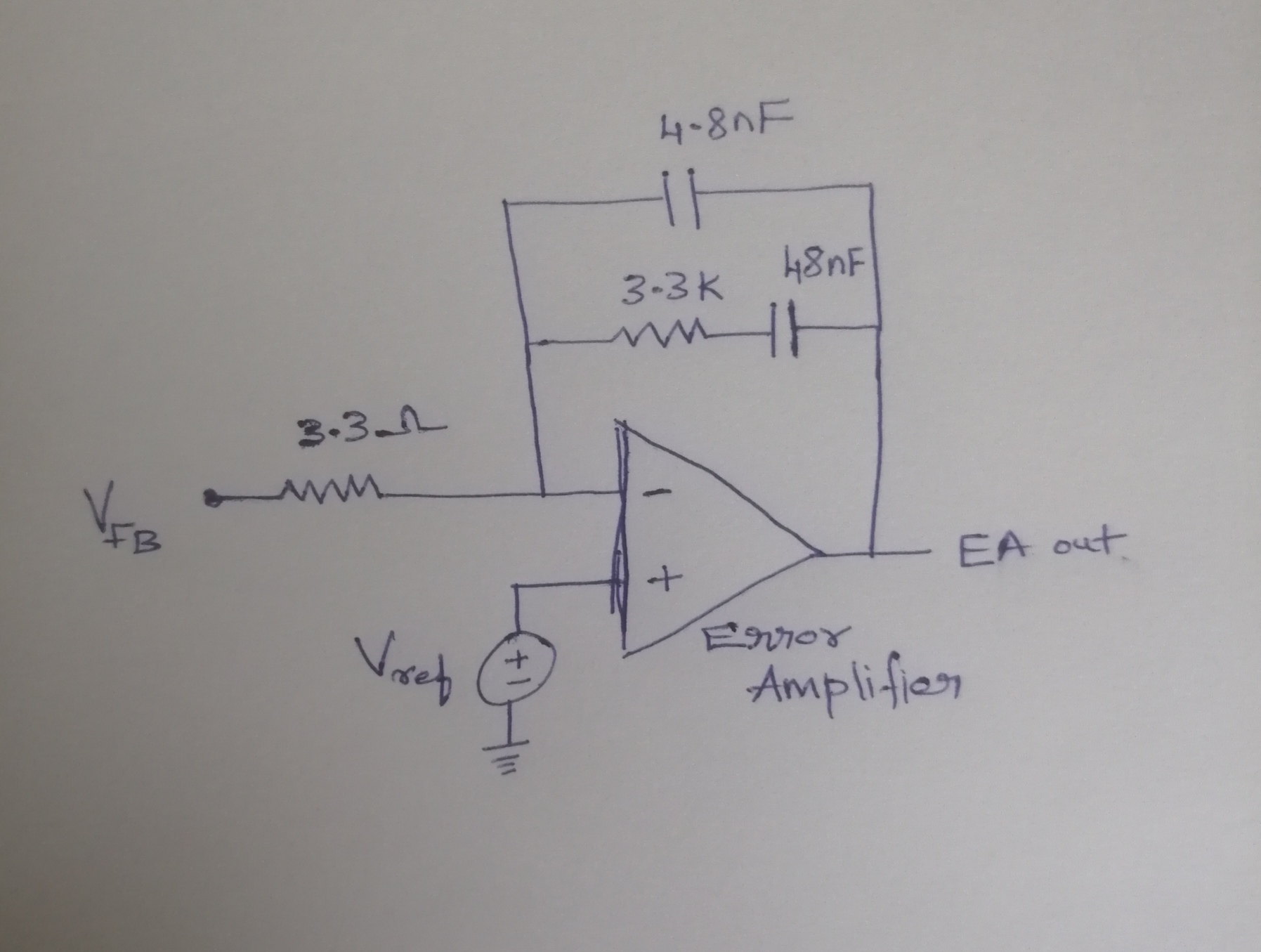
I am using UC3825.I want to understand about the internal operation of the error amplifier.Can you explain it ?

  • Greetings,

    The UC3825 internal error amp has all three terminals available for maximum user flexibility. A dc reference voltage is applied to the non-inverting input (pin 2). The regulated output voltage is divided down and fed back (typically through an optocoupler) to the inverting error amp input (pin 1). The divided down feed back voltage is compared to the reference voltage and the difference is multiplied by the gain of the error amp. The compensation network can be simple if the UC3825 is set up for current mode control (CMC) or more complex if configured for voltage mode control (VMC). The method and type of compensation built around the error amp (feedback applied between pins 1, 3) plays an important role for determining the stability, voltage regulation and bandwidth of the power converter. The output of the error amp is used as the inverting input to the PWM comparator and compared to the non-inverting PWM comparator input. The signal applied to the non-inverting PWM comparator input can be either the CT (pin 6) for VMC or the sensed current from the power stage for CMC. For more detailed information about voltage error amps in switching power supplies, check out: Error Amplifier Limitations in High Performance Regulator Applications.

    Regards,

    Steve M

  • Thanks for your explanation,but i have another doubt.

    If the reference(non inverting) of error amplifier is 2.5 V,the inverting pin voltage will start from zero,so the differential error voltage should start from 2.5 V and it starts decreases and once the inverting pin voltage reaches 2.5 V it reaches zero.But in my case,the error voltage starts from zero and when it reaches the 2.5 V,it becomes zero.Is this correct? 

  • Hi,

    Everything you said is true, if you disregard soft start. Without soft start capability, the differential input voltage to the error amp is initially 2.5V at start-up. The error amp has high gain which would drive the output into saturation causing the output to rail HIGH. Thanks to soft start, the operation is as you described: The error amp output starts from 0 V until it reaches the PWM control voltage (Ramp peak or CS+slope comp peak) where it settles tot he control voltage based on the loop gain, and input and output converter operating conditions.

    Regards,

    Steve M

  • Thank your explaination about EA.

    i have used type 2 compensator for this error amplifier and the values are mentioned in the about picture.

    Vfb = (0 to 5)V  Vref = 5 V

    So,i have got the gain of the compensated error amplifier as Gain = 3.3k/3.3 = 1000 .

    EAout = (Vref - Vfb) * gain.

    Based on the above formula,when i set the reference as 2.5 V and the Vfb starts increasing,the error between these will be multiplied by 1000 and so the error amplifier output will be saturated.Is this correct?

  • But the gain value is large as 1000.It may lead to saturation even at low error value.

  • Yes, an error amp like any op amp has a Gain BW limit to how much we can demand from it. We desire the error amp to have high gain at low frequency and low gain (attenuation) at high frequency. Within the UC3825 product folder there is Application Note U-110 which details how to configure the error amp and compensation. Once you decide on a topology and control method, there are many good resources far learning how to compensate control loops. SLUP340 is one example. I am going to close this thread because I believe we have discussed and answered your original question about how the error amp work. Thanks for using TI e2e and good lucj with your design.

    Regards,

    Steve M