This thread has been locked.

If you have a related question, please click the "Ask a related question" button in the top right corner. The newly created question will be automatically linked to this question.

LM3445: questions about LM3445

Part Number: LM3445

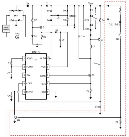
Hi,I don't find the description of OVP and softstart in LM3445 datasheet.How can I achieve OVP and softstart fuction with extra components?

  • Hello,

    Soft-start is created by default with the FLTR1 and FLTR2 capacitors to filter out the 100/120 Hz line component.  OVP was not considered for this design, it can be added.  This part started out as a controller for a buck converter.  The output cannot go higher than the input voltage.  What circuit are you interested in using, the buck with valley fill or other topology?

    Best Regards,

  • Hello,

    Thanks for your reply.I'm intersted in using buck topology with valley fill.I made a test board refer to "AN-1935 LM3445 Off-Line TRIAC Dimmer LED Driver Demo Board" for test.I'm worried about the safety of output filter capacitor when LED open circuit occurs.If OVP can be added,I can use low voltage and smaller size output filter capacitor.Could you tell me how to add OVP?

    Best Regards,

  • Hello,

    One example is to use a circuit similar to the off-time PNP, Q3.  This is an additional circuit that would use a resistor with a lower value than R4 and a series zener to set the OVP level.  Instead of a capacitor like C11 it would be a resistor that ties to an NPN transistor base that shunts FLTR2 (have to watch the leakage of the NPN since FLTR2 is high impedance).  An additional power zener or TVS would be needed across the output to shunt the minimum on-time current from causing the output to rise (this is low power since FLTR2 would be shunted).  This zener or TVS needs to only conduct current after the OVP circuit is active otherwise it will have to dissipate too much power.  This means it's clamping voltage needs to be higher than the OVP circuit threshold.

    There are many ways to create an OVP circuit that will protect the output voltage from rising too high.

    The other option is to use a 200V capacitor at the output.

    Best Regards,

  • Hello Irwin,

     Here is my understanding of OVP circuit according to your idear :When OVP occurs,voltage of R5 increase,then Q5 open. 

    This will  pull down voltage of FLTR2.The driver operates at light load mode.Out put voltage is clamped by D11.

    Is below OVP circuit correct?If it's not correct, how to modify?

    About the softstart,I try to increase FLTR1 and FLTR2 capacitors,but I find it has no obvious effects.

    Is there any method to adjust start up time?

    Thank you!

  • Hello,

    Yes, that is what I meant.  D12 needs to be a higher voltage than the LED string voltage, D11 needs to be a higher voltage than D12.

    What do you specifically mean by start up time?  What do you want it to do?  This part has a minimum on-time so it will provide a little current to the output even when FLTR2 is low.

    there is a time constant with FLTR1 and FLTR2, 370 Kohm for FLTR2 with the capacitor C4.  For FLTR1 it's R1 and C3.  To slow down start-up you could place a resistor and capacitor in series with D1.  The resistor would be a high value just to allow discharge of the added 'C' (note that if you are triac dimming this could add light flash at lower dim levels when turning on.

    If you watch the LED current there will be a delay and rise time that will change if the FLTR2 capacitors are changed.  What values are you using for the FLTR capacitors and R1.

    Best Regards,

  • Hello,


          The values of  FLTR capacitors is 0.22uF.R1 is 100kΩ.

    Now I find a problem: There is a mechanical switch on the triac dimmer.When turn on the dimmer,I can find  a little flash.

    Please see the following waveform

    I think the driver start up quickly that caused this flashing.So I want to adjust the start up time.

    I try to increase Vcc capacitor and place a resistor in series with Vcc capacitor.Start up time increase,but I still find this flashing.


    Perhaps add quick discharge circuit to VCC maybe solve this problem.But it will cost up.

    Do you have easy way to solve this flashing problem?

    Thank you very much!

  • Hello,

    This isn't really a soft start issue.  What is happening is the LM3445 is still active (on) without any current to supply to the LEDs.  When some energy comes in through the input the LM3445 immediately starts running.

    Is this really an issue?  Powering down for 100 ms and then back on?  Have you tried other dimmers?  It's possibly to change the timing of the LM3445 to make this go away but it may just show up at a different on/off/on time.  You may also run into other issues when deep dimming.

    Can you zoom in on several of the 'mechanical noise' of the switch?  It would be helpful to know what has to be ignored.

    Best Regards,

  • Hello:

    I tried other dimmers.but I don't find this issue.I think just this dimmer can find this issue.I try to add below circuit between VCC and FLTR2.

    The flashing problem is solved,but I find other problem: the voltage of FLTR2 increase

    Do you know the reason why voltage of FLTR2 increase?

  • Hello,

    What NPNs are you using?  You have to be careful using circuits like this, Vbe is temperature depending  so R3/R4 divider set-point will change over temperature.

    FLTR2 is high impedance from a DC standpoint.  If non-symmetrical noise or leakage current goes to that pin the voltage will change.  Looking at your circuit I would think it wouldn't pull FLTR2 that high up.  Remove the Q2 connection and measure the collector voltage and see what it is.

    Something is sourcing current into FLTR2 pin, it is only pulled up to 0.75V internally.

    Are you sure you want to add a circuit to prevent this flash for one dimmer only when turned off and on fast?

    Best Regards,

  • Hello:

    Remove Q2 connection,voltage of FLTR2 pin is 0.75V.

    Unfortunately,compatible with the problematic dimmer is our customers' requirement.

    I find the same issue if add OVP circuit.Do you have any other idear for OVP?

    Next step,I will try to connect previous circuit to DIM pin, so it won't affect the voltage of FLTR2 pin.

    Thank you!

  • Hello,

    I do the test that connect a NPN to FLTR2 pin with the base grounded.

    I find the voltage of FLTR2 will also be changed:

    Could you tell me the reason?

    Thank you!

  • Hello,

    What NPNs are you using?  You could try using something like a BSS123 instead, just for the one connected to the FLTR2 pin.  It's high impedance but not that high, it should work.

    Best Regards,

  • Hello,

    What NPN are you using?  Is FLTR2 voltage going up as before?  That shouldn't be possible unless noise is getting into the circuit.

    Best Regards,

  • Hello,

    I am using 2PD601ART(NXP 50V 100mA).

    With the base grounded, transistor Q5 is a very high impedance.

    Voltage of FLTR2 pin should be limited to 750mV.But it increase to 1.1V if connect Q5 to FLTR2 pin.


    It is confusing.Could you help to find the reason ?

    Thank you!


  • Hello,

    If the base and emitter are at ground and the collector tied to FLTR2 it cannot source current into FLTR2 so something else is causing FLTR2 to rise.  Either noise is coupling in or the connection(s) to the board are not correct or something else is connected to FLTR2.

    Best Regards,

  • hello,

    I try to put a small capacitance capacitor in parallel with C-E of NPN or move NPN close to FLTR2 pin,the voltage of FLTR2 is not rising.Flashing issue is also improved .I think,as you had mentioned before,noise is getting into the circuit.I have one more question.To reducing Noise of FLTR2,when I make PCB layout,what should I pay attention to?

    Thank you!

  • Hello,

    The high impedance, DC wise, is FLTR2 so I would place the NPN close to the FLTR2 pin and make sure the ground return is near the IC and FLTR2 capacitor.

    Best Regards,