This thread has been locked.

If you have a related question, please click the "Ask a related question" button in the top right corner. The newly created question will be automatically linked to this question.

TPS62745EVM-622: Create a negative voltage.

Guru 10615 points
Part Number: TPS62745EVM-622
Other Parts Discussed in Thread: TPS62745

Hi team.

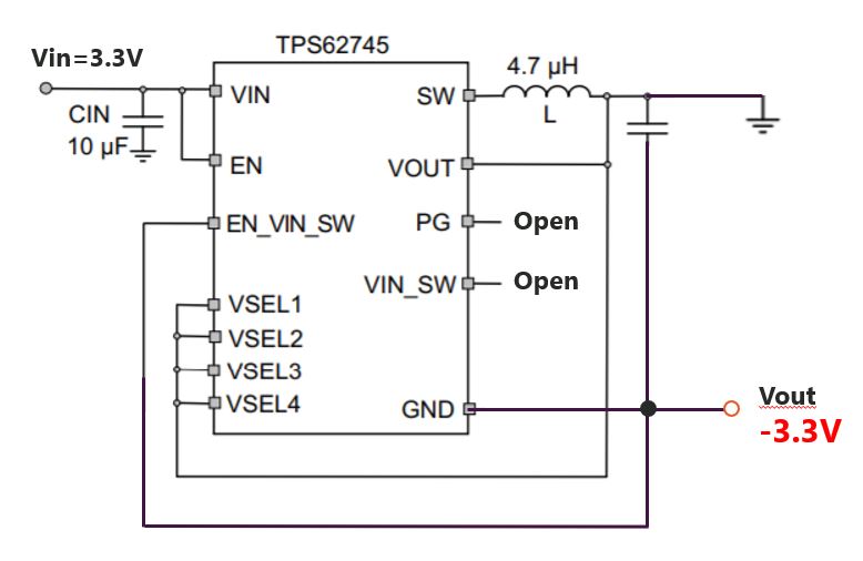
I'd like to make a negative voltage of TPS62745.
I refer to this material(https://www.ti.com/lit/an/slva458b/slva458b.pdf).

Could you tell me my questions?

1. Can I make a negative voltage of TPS62745?

2. How can I process of TPS62745EVM to produce a negative voltage?

3. If TPS62745 can not create a negative voltage, could you tell me why I can not make a negative voltage?

4.Could you introduce me to a device where Iq can generate a negative voltage as low as TPS62745?

Sincerely.
Kengo.

  • Hi

       Can you please let us know your Vin, Vout and Iout requirements for your application? Can you let us know what is the load that you are planning to power with this device?

    Regards,

    Gerold

  • Hi Gerold,

    Vin=3.3V
    Vout=-3.3V
    Iout=10mA

    We plan to power DMOS FET.

    Sincerely.
    Kengo.

  • Kengo,

    These application conditions can work with the TPS62745.

    For more information on how to create a negative voltage with a buck converter please refer to the thread and tech doc links below:

    https://e2e.ti.com/blogs_/b/powerhouse/archive/2018/05/16/how-to-modify-a-step-down-converter-to-the-inverting-buck-boost-topology

    http://www.ti.com/lit/pdf/tidud32

    Sincerely,

    Matt

  • Matt,

    Thank you so much for your advice.

    TPS62745 has VSEL pin.
    How to connect to VSEL when creating 3.3V negative voltage?
    Is it OK, if I connect  VSEL to Vout as same as the EVM?

    If NO, I use an external supply for VSEL.
    Does it have a power up sequence with Vin/Vout/VSEL?


    And then, could you tell me about inductor selection and SW frequency?

    About Inductor selection,
    My customer application needs only 1mA or less.
    How to set output inductor?
    It will be a very large value when calculated normally.

    About SW frequency,
    What is the SW frequency when the current is less than 1mA?
    I can not read the graph on the datasheet.

    Sincerely.
    Kengo.

  • Kengo,

    Yes, you can connect the VSELn pins to "VOUT" as on the EVM.

    I'm still looking into the inductance value and switching frequency for you, but given the extreme light load conditions, this is going to be dependent on the TPS62745's ~250ns minimum On-time.

    Sincerely,

    -Matt

  • Matt,

    Thank you so much for your reply.

    Is this circuit diagram correct for the negative voltage?


    Could you tell me about the inductance value and frequency at the light load as soon as possible?
    My customer wants to complete the circuit diagram quickly.
    Could you give me an answer by 9/3(in US time)

    Sorry to bother you while you’re busy.

    Sincerely.
    Kengo.

  • Hi

       Matt is looking into this.

    regards,

    Gerold

  • Kengo,

    The diagram above is correct.

    As for the inductor value, 4.7uH is the largest recommended inductance value for TPS62745 designs.  

    Given the extreme light load (<1mA), the device will be forced to operated in its Power Save mode, and the ~250ns minimum ON-time combined with this inductance value will ultimately determine the switching frequency.

    For a 4.7uH inductance, the delta-I during Ton will be: (Vin/L)*TONmin = (3.3V / 4.7uH)*250ns = ~175mA

    In turn, in order to maintain ILavg = Iload = 1mA, the effective duty cycle will need to be ~0.6%, which would put the switching frequency at ~24kHz.

    Please also note that I found that our PSpice model for the TPS62745 is giving me a 400+ns Ton for this IBB configuration, which generatesa 275mA Ipeak and ~19kHz switching frequency. 

    Sincerely,

    -Matt

  • Hi Matt,

    Thank you so much for your reply by 9/3 US time.

    I understood about inductance and Fsw.

    Could you tell me about the connection of GND?
    Can I make all the orange circles(GND) common?
    If I should separate, please let me know.


    By the way, is the EN_VIN_SWpin connected properly?
    I do not use Vin_SWpin so EN_VIN_SW needs to tied to GND, right?

    Sincerely.
    Kengo.

  • Kengo,

    Yes, your GND connections are correct, and they can be common.

    I noticed that you added the LDMOS Off of the -Vout, and I’m assuming this would be for use as a power good indicator.

    Please refer to the below tech doc for more information on how to level shift the PG signal:

    Sincerely,

    Matt

  • Hi Matt,

    I'd like to discuss with you about switching noise on SWpin.

    My customer gets a waveform using a modified EVM to create a negative voltage.
    I'm sorry it is hard to see.

    Green : SWpin(1V/div)
    Yellow : Vin(2V/div)


    I see a switching noise when the output is rises.
    Why does it appear?
    Is it because GND is weak?

    Sincerely.
    Kengo.

  • Kengo,

    Yes, this is an artifact of the system GND being tied to the converters LC output filter (Vout+), and our EVMs are not optimized to offer a good means of making a low impedance connection between Vout + and Vin -.  So, I suspect that you are seeing ringing associated with this connection (clip leads?). 

    You should find that you can get cleaner waveforms if you use the chip GND (Vout -) as your scope GND reference, but ultimately the design will need to have a good low impedance system GND connection for proper operation.

    Sincerely,

    -Matt