


Dear TI Team,
I have some questions about the WATCHDOG TIMER IC.
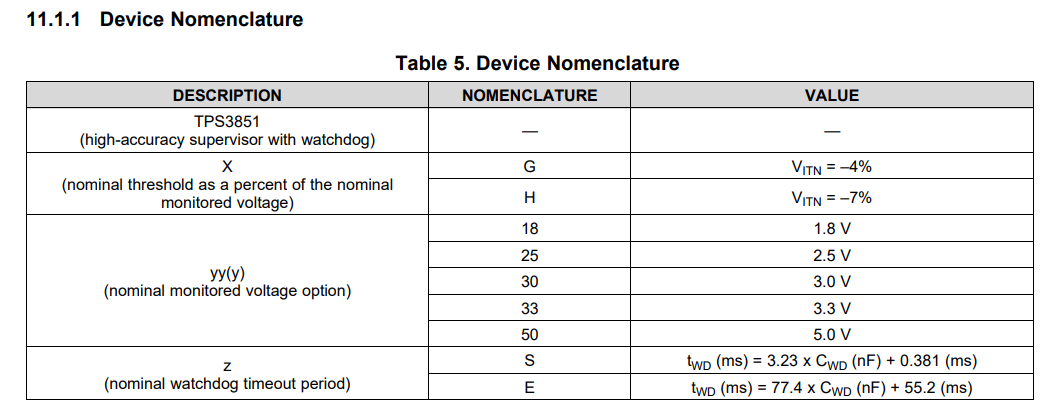
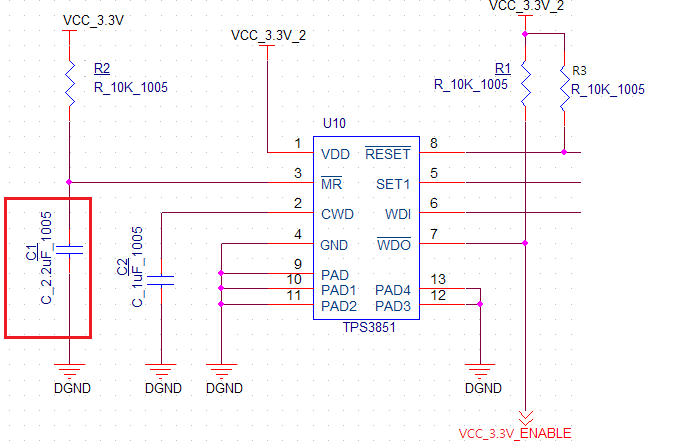
The WATCHDOG circuit is composed as follows.
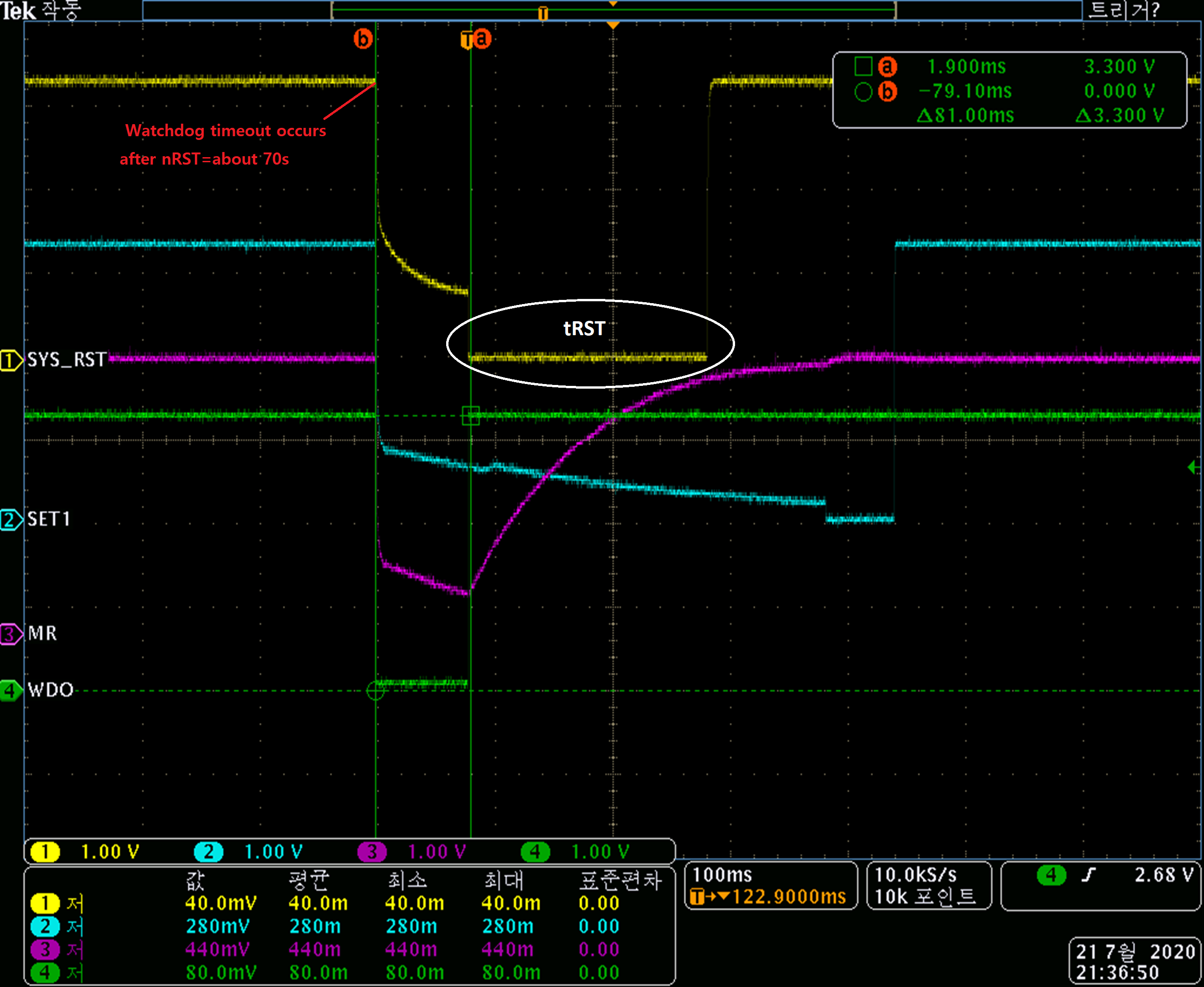
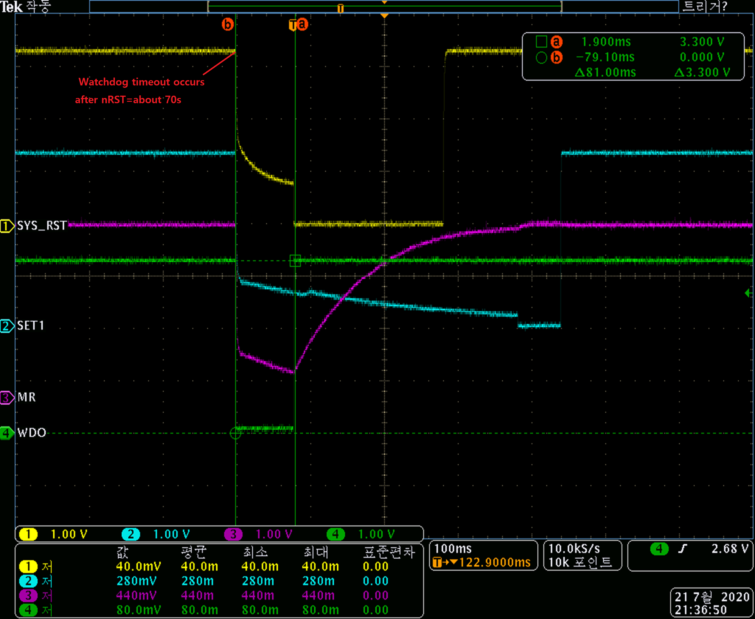
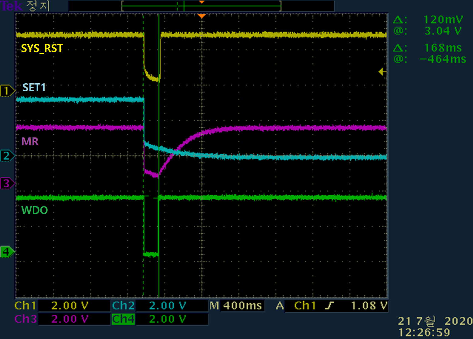
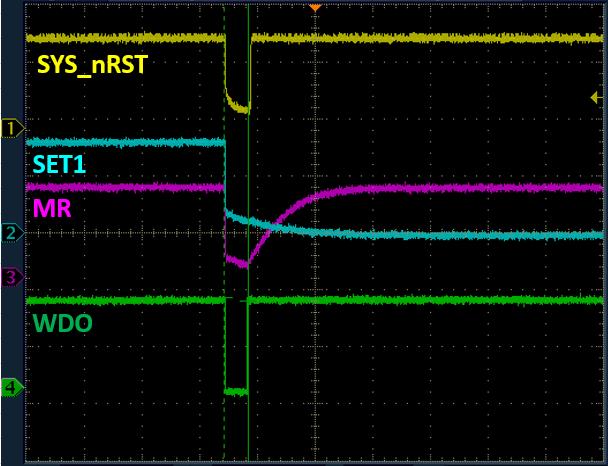
The experimental results are as follows.
(b) It is a situation where the Watchdog timeout occurs after nRST=about 70s has passed before the section.
It is connected with'SYS_RST = /RESET pin, SET1 = SET1 pin, MR = /MR pin, WDO = /WDO'.
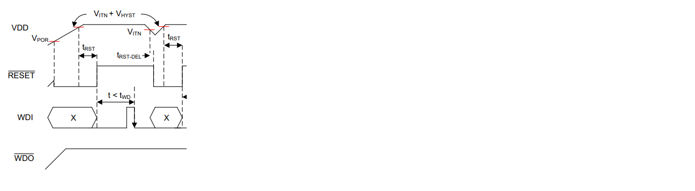
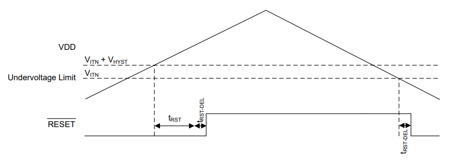
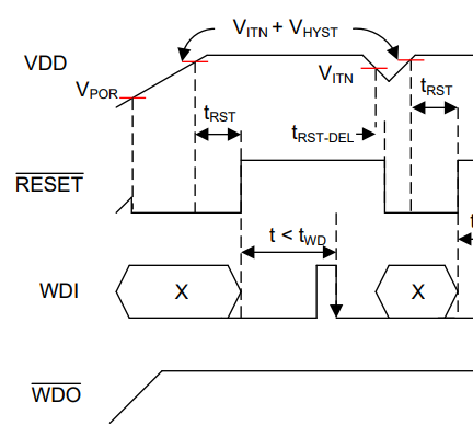
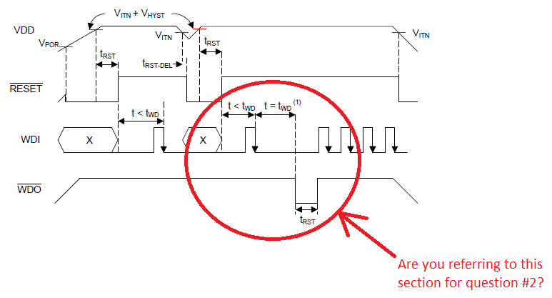
Question 1. SYS_RST(/RESET) slightly falls as much as the section where MR LOW becomes, then fixed tRST=200ms low and then turned high again.
What is the voltage drop in section (b-a)? Is it right waveform?
Question 2. The section where /MR changes from Low to High is known after the /RESET signal passes tRST. Is it correct? In this image, it seems that the tRST and /MR High progress intervals are similar.
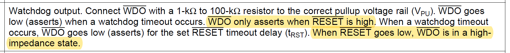
Question 3. Asks whether the timing of /WDO operation is also normal.
Thank you very much.


