This thread has been locked.

If you have a related question, please click the "Ask a related question" button in the top right corner. The newly created question will be automatically linked to this question.

TPS53622: Intel CPU with TPS53622 power supply measurement VRTT & Bode plot issue

Part Number: TPS53622

Hi SIR

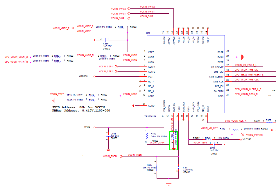
Our product is designed with Intel CPU and matched with TPS53622 power supply.
The circuit and  Bode plot and POL Transient diagrams and specifications are as follows~~
Input : 12V 
Output : 1.82V  (two phase)
Iout : 55A
Fsw : 800kHz
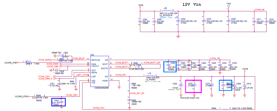
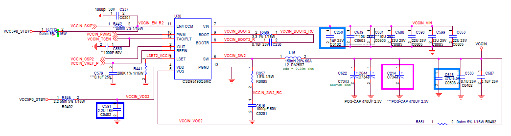
Cout : MLCC  47uF 6.3V 0603  45pcs  +  POSCAP  470uF 2.5V ESR:3 ohm   4pcs  

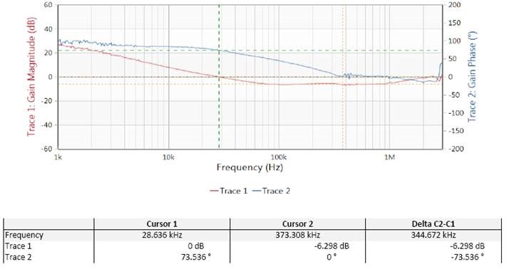
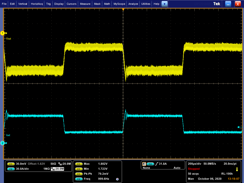
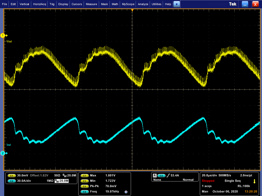
During the verification of VRTT and Bode plot , adjust the compensation parameters of the TPS53622 controller.
It is expected that VRTT can meet the specifications of Inter CPU, and the Bode plot can be P.M. >45 degrees & G.M. >-10dB specifications.
There are some challenges for both to meet specifications at the same time. The TPS53622 controller is adjusted to the best parameter values.
Most of the VRTT test results are on the critical edge, so we are currently testing the Bode plot after the VRTT passes.
The best set of TPS53622 controller parameters are as follows.
Although VRTT passes, the G.M. of the bode plot is about -6.2dB.

AC_Gain : 2.0 
AC_LL:2.375
INT_TIME:5
INT_GAIN:2.0
RAMP: 280mVp-p


If the CPU VRTT verification of the POL load side is passed, can the VRTT verification be used to replace the problem of BODE PLOT G.M. being less than -10dB?

  • Hi Kao,

    Thanks for the detail. If there is -6dB gain margin and intel test plan is passing, I don't see any need to modify the compensation parameters.

    Thanks

    Chasel

  • Hi Chasel

    The VRTT Test rule applicable to Intel CPU includes dynamic load characteristics of various frequency bands.

    If the compensation parameters set by TPS53622 POL can meet the electrical requirements of the transient load in various frequency bands of the CPU, although the Bode plot gain margin is only -6.2dB, the compensation parameter design of the controller has already met the best conditions for stability.

    The above are the concepts we understand to explain to our customers.
    TI power management IC is used in the power supply of the CPU. Does TI have relevant reference documents or research that can explain that VRTT can replace the bode plot measurement to verify the stability?

    In this way, we can also easily explain to customers.

    Thank you.

  • Hi Kao,

    The stability criteria cannot be judged by only referring to bode plot result, so that you need to check the large signal test like intel test plan.

    The simple way to check the stability of TPS53622 is to check the static load PWM jitter, if you can see the successive two PWM pulses with minimum off time on either phase, then it is considering as unstable. In such case, you shall see huge voltage ripple at output side and it may fail the design target.

    From the body plot perspective, what we expected is, the phase margin is with enough margin (>45degree), and the gain margin is >-6dB, that shall tell the design meets the expectation.

    Hopefully the explanation makes sense.

    Thanks.

    Chasel