This thread has been locked.

If you have a related question, please click the "Ask a related question" button in the top right corner. The newly created question will be automatically linked to this question.

BQ24650: Power switch off issue still occurs with battery protection circuit

Part Number: BQ24650

Hello,

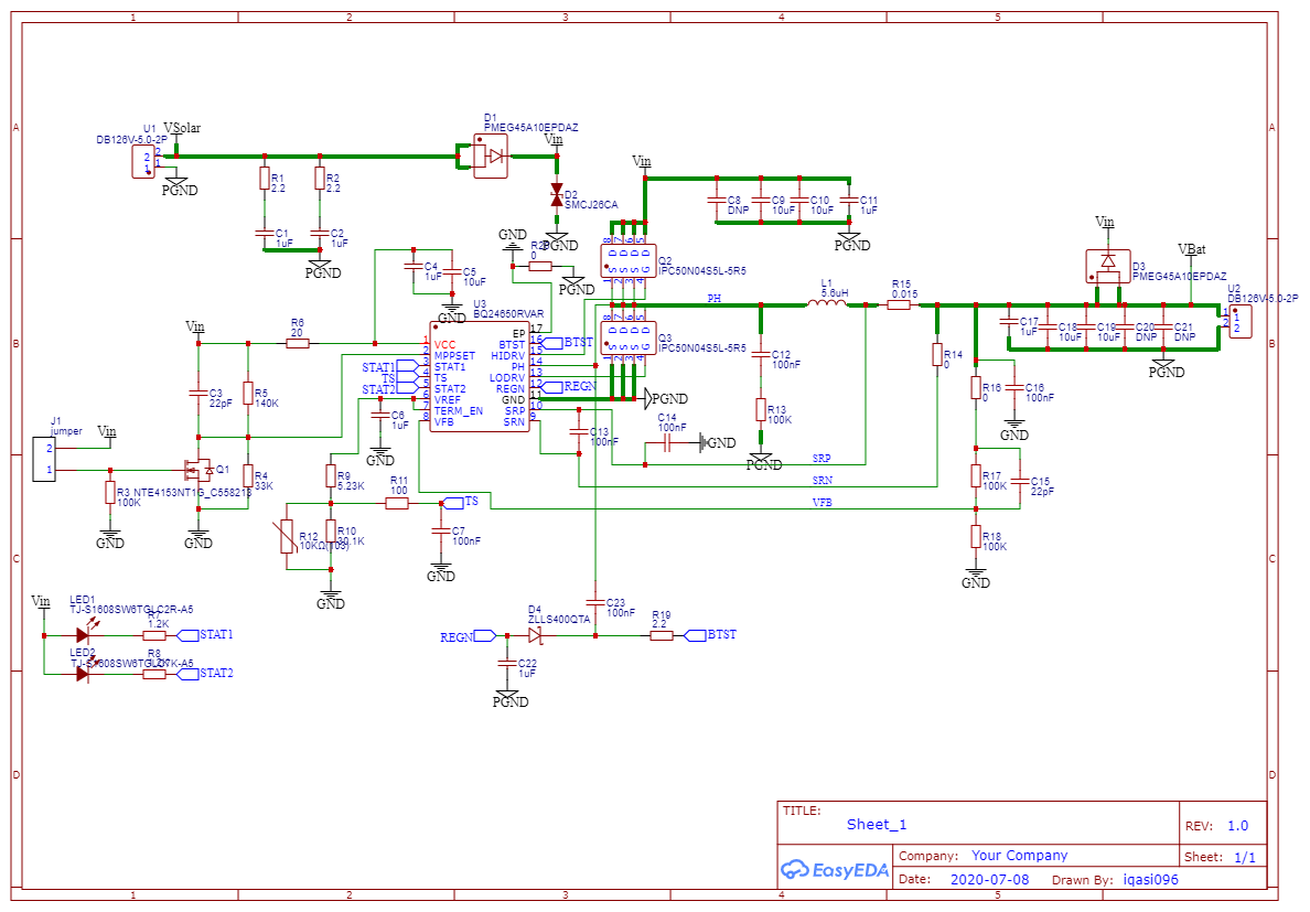
I have recently posted about an issue with the BQ24650 chip in supplying a continuous load while charging from a solar panel here: e2e.ti.com/.../945377. I have designed a battery protection circuit with an FS8205 MOSFET and DW01+G protection chip to prevent my battery from completely being depleted and triggering a cutoff. The design will however gives me the same issues with my protection circuit being connected to the VBat output (found below). Once my battery runs out of charge as providing a load of a low power MCU and step up converter, could it be causing a large voltage drop at the output of the BQ24650 chip and thus triggering the built in precharge timer??

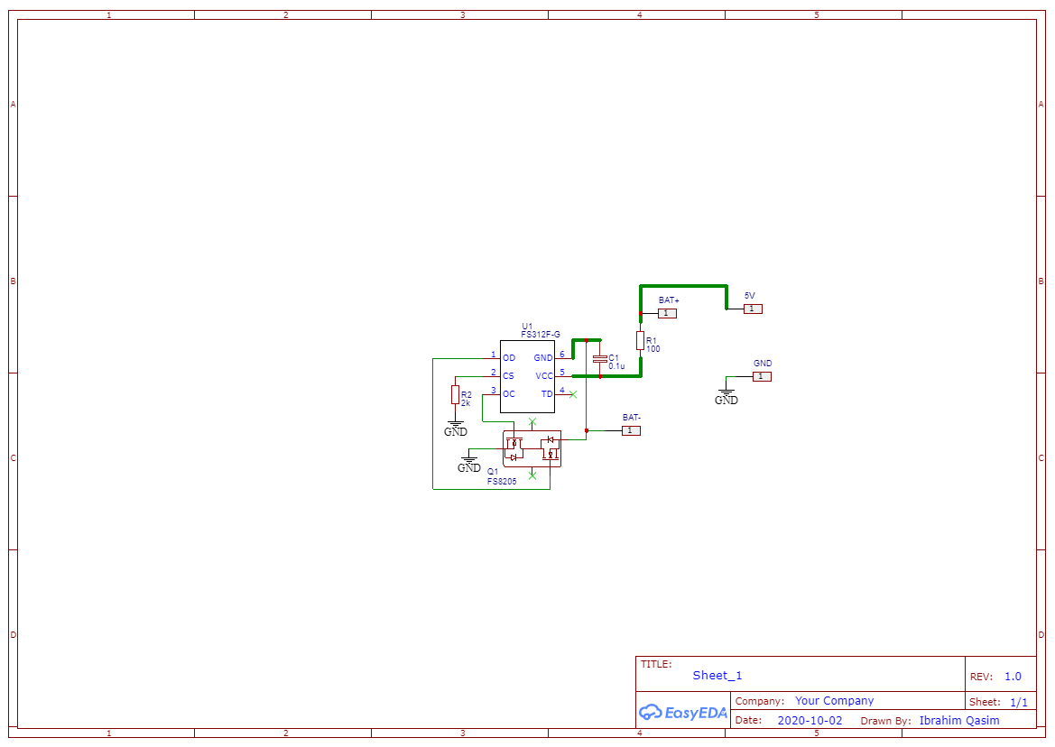
Note: The overdischarge protection voltage is at 2.4V and its release voltage is 3.0V.

Here is the battery protection schematic & charging board schematic for reference: 

And here are the datasheets of the components used:

FS8205 dual channel MOSFET: 

https://www.ic-fortune.com/upload/Download/FS8205-DS-19_EN.pdf

FS312F-G DW01+G Battery protection IC: 

https://datasheet.lcsc.com/szlcsc/1810101017_Fortune-Semicon-DW01-G_C14213.pdf

Thank you!

  • Hi Ibrahim,

        Based off of your 1S charge regulation voltage, the VLOWV threshold (1.55V on VFB pin) is equivalent to 3.1V of your real battery voltage. If the load causes the battery voltage to discharge below this voltage, then if adapter is ever connected while VBAT < 3.1V, the charger will charge in precharge mode and the 30 minute precharge safety timer would be active.

  • Hey Kedar,

    I am a little confused, when I checked the VFB voltage when the battery was in a deep discharge, it was 2.0 V and the real battery voltage was around 2.4 V. So is my battery protection chip not sized properly for my battery in unison with the BQ24650 chip??

    Thank you,

    Ibrahim

  • Hi Ibrahim,

        Instead of monitoring with VFB a multimeter, can you take a scope capture of PH and SRN? When the battery pack protector FET open due to being discharged, I want to verify whether the part is entering battery absent detection.

  • Kedar Manishankar said:

    Hi Ibrahim,

        Instead of monitoring with VFB a multimeter, can you take a scope capture of PH and SRN? When the battery pack protector FET open due to being discharged, I want to verify whether the part is entering battery absent detection.

    Hello Kedar,

    My apologies as I do not possess an Oscilloscope at my workplace due to Covid restrictions. I did however deduce that my issue is gone once i disconnect all my loads. By that I mean I disconnected my battery charging module, solar panel, battery, and battery protection IC from my 5 V step up converter which leads to the loads of my system. In doing so, the battery is able to accept charge and recharge to its full state without the need of restarting the charge cycle manually.

    I have provided a visual representation of my system to better understand its elements.

    I hope some of this information is useful in diagnosing my issue:

  • Hi Ibrahim,

       If you disconnect the load form the battery, this should allow the battery to be fully charged. The reason you have to restart the charge cycle manually is because your load is causing your battery to be discharged, so when the VFB < 1.55V, the charger will begin the charge in precharge mode. In this mode there is an inbuilt 30 minute precharge timer after which a fault condition will be indicated and charging will stop. You will need to restart the charge cycle manually in this case.

  • Hello Kedar,

    Although one of my loads is continuous, it pulls around 0.2 Watts which I presumed to be very little. Is there a way I can fix it so that my battery charging circuit and my battery will disconnect from the load completely at 2.5 V of the Lipo battery automatically without the need of a manual reset ?? I have implemented the battery protection circuit to amend this but the issue still occurs. May you review my model or possibly suggest a fix I can implement from some of the TI ICs??

    The circuit above merely switches the negative terminal of the battery between the IC GND and the common GND (the PGND of the battery charging circuit and load), causing the battery to disconnect at cutoff voltages of 2.5 V and release at voltages of 3.0 V. You are saying there is a possibility of my load draining my battery and not allowing the battery to charge. Is there an issue in my design?? I see this battery protection circuit as the key to my issue and I feel like there may be a flaw in my design

  • Hi Ibrahim,

      Can you set the cutoff voltage threshold higher than 2.5V. Maybe to about 2.8V or 3V?

  • Hello Kedar,

    I cannot change it with the current IC I possess. I will need to order another IC (FS312F-G) with the following specs: datasheet.lcsc.com/.../1811151452_Fortune-Semicon-FS312F-G_C82736.pdf and it will take some time to ensure whether the higher cutoff voltage will work as I am in Canada and the IC is being shipped from China. On another note, I have accepted the fact that I will always have an ever-present load on the battery side of my BQ24650 charging solutions and another solution I have considered was using a manual switch to cause an open circuit which would isolate my battery from my load. My issue with that however is that I will not be able to measure my battery capacity with my MCU and current sensor accurately so I may need to spec some sort of coulomb counter IC. Would the BQ27441-G1A be a possible IC to accurately measure my battery capacity??

    Thank you,

    Ibrahim   

  • Also I was looking at the possibility of my battery protection circuit lowering the battery voltage below the VLOWV threshold which could also be causing the chip to enter precharge mode. How would the BQ24650 chip know whether the battery has been disconnected or whether it is discharged to a low voltage??    

  • Hi Ibrahim,

       Regarding the BQ27441-G1A I would create a new post with that part number in the title so the expert supporting those parts can answer your question. BQ24650 has battery absent detection, and the detection scheme can detect if battery is absent as it will observe the output capacitors charging and discharging quickly. Precharge mode is when the battery voltage sensed on VFB is < VLOWV.

  • Hello Kedar,

    It seems that the battery protection circuit would still cause issues as the results from my test over the past 2 weeks has shown. When referring to the schematics of my battery protection circuit and charging board above, it seems that when I connect the BQ24650 charger output (VBat and PGND) in parallel to the battery protection circuit's output (5 V and GND) the battery would be discharged to 3.0 V and one of the dual n channel mosfets would trigger indicating an overdischarge condition. If the load remains connected for an hour or so, this condition would cause the output to be reduced to 1.6V and thus triggering VFB < VLOWV over time. If load is disconnected as soon as this happens and there is ample solar exposure on my PV, charging would resume and battery would charge.

    I also tried connecting the BQ24650 charger output (VBat and PGND) to the battery protection circuit's input (BAT+ BAT-) in parallel with the battery, once the protection circuit enter overdischarge mode, I have no means to trigger the mosfet and allow for discharging again, so I would have an issue on the other end of my battery. 

    I am not sure if my diagnosis is accurate so in the meantime, I have decided to move away from the current architecture and use a 3 V MCU load before my 5 V converter leading to my other loads and attach a comparator with hysteresis to sense the voltage of my battery where my VH = 4.2V and VL = 3.0V. My new architecture would look something like this:

    LTC config (3).pdf 

    Could you please suggest a non inverting comparator reference appropriate for my application?? Does this sound like a reasonable solution??

  • Hello Kedar,

    I must ask whether my connections are correct or not. I tried to connect the battery to my protection circuit with 2 methods and here were the problems I encountered:
    1) I connected the battery charger in parallel with the bat+ and bat- points (located in my schematic) which were connected in parallel with my battery. I noticed that this would be the only method to charge my battery when the dual channel mosfet triggers due to the VFB<VLOWV precharge mode condition found in the BQ24650 chip otherwise [Explained in point (2)]. The issue comes when discharging as I have no way to trigger the OD MOSFET back on to allow for discharging.
    2) I tried connecting the battery charger in parallel with the 5V and GND points (located in my schematic) while my battery is connected to the bat+ and b- points. I noticed that I will be able to discharge just fine as long as my battery is in charge mode, the issue comes when charging my battery after the OD protection triggers causing the battery charger to go into precharge mode (since VFB < VLOW) and the voltage at 5 V and GND causes the precharge mode condition. So the charger thinks the battery is absent or is deeply discharged and disables charging.
  • Hi Ibrahim,

       In battery absent, the charger still has a 500ms deglitch time during which 125mA is supplied. The main issue is with the system requirements, as if the battery charger cannot charge the battery past VLOWV within 30 minutes then a fault condition is triggered. This means that the system requirements are causing the battery to discharge too deeply.  If using a comparator, you can set the output to toggle CE whenever battery voltage < VLOWV. This ensures that a new charge cycle is initiated while VFB<VLOWV so that the precharge timer gets reset. 

  • Hello Kedar,

    I was looking at the comparator as more of a undervoltage cutoff at the output of the BQ24650 charger to disable the load at a VL threshold and enable it at a VH threshold with a hysteresis between them to ensure stable operation. Would this be a more feasible approach?? 

    Thanks,

    Ibrahim

  • Hi Ibrahim,

      This would work too. The essence of the issue is the load is too high for the application, causing the battery to discharge too low, and the charger IC is not able to charge at precharge current for 30 minutes to raise VFB voltage above VLOWV. You can also set a higher precharge current using the voltage on the ISET2 pin, if it is within safe charging conditions as specified by your battery manufacturer.