- Ask a related questionWhat is a related question?A related question is a question created from another question. When the related question is created, it will be automatically linked to the original question.
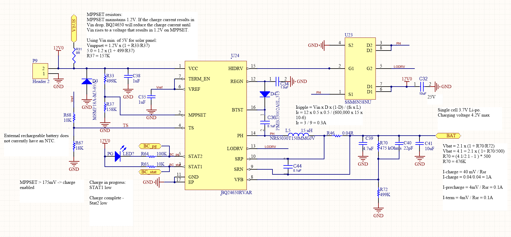
Please see the schematic screenshot attached.
Vin: 12V (DC Adapter) or 5.0V coming from USB
Vbat: 3.7V lipo (4.2V max charging voltage)
Measured:
Vref: 3.3V
Vcc: 12/5V
MPPSET: 1.2 (with a 5V source), 2.94V with a 12V source
TS: 1.6V and 2.19 V (tried 2 different R67 values)
LODRV has pwm pulses
V-regn : 6.0v (with a 12V source), otherwise 5.0 with a 5V source
Vfb: 1.95V (Vbat = 3.93V), charge termination voltage set at 4.1V
The stat1 pin is pulled low (LED on) while stat2 pin is high indicating that charging is in progress but the Vbat remains at battery level and battery never charges. I am not sure what I am missing or doing wrong.
Please help me identify the issue.
Thanks in advance.
Noaman
PH Pin waveform:
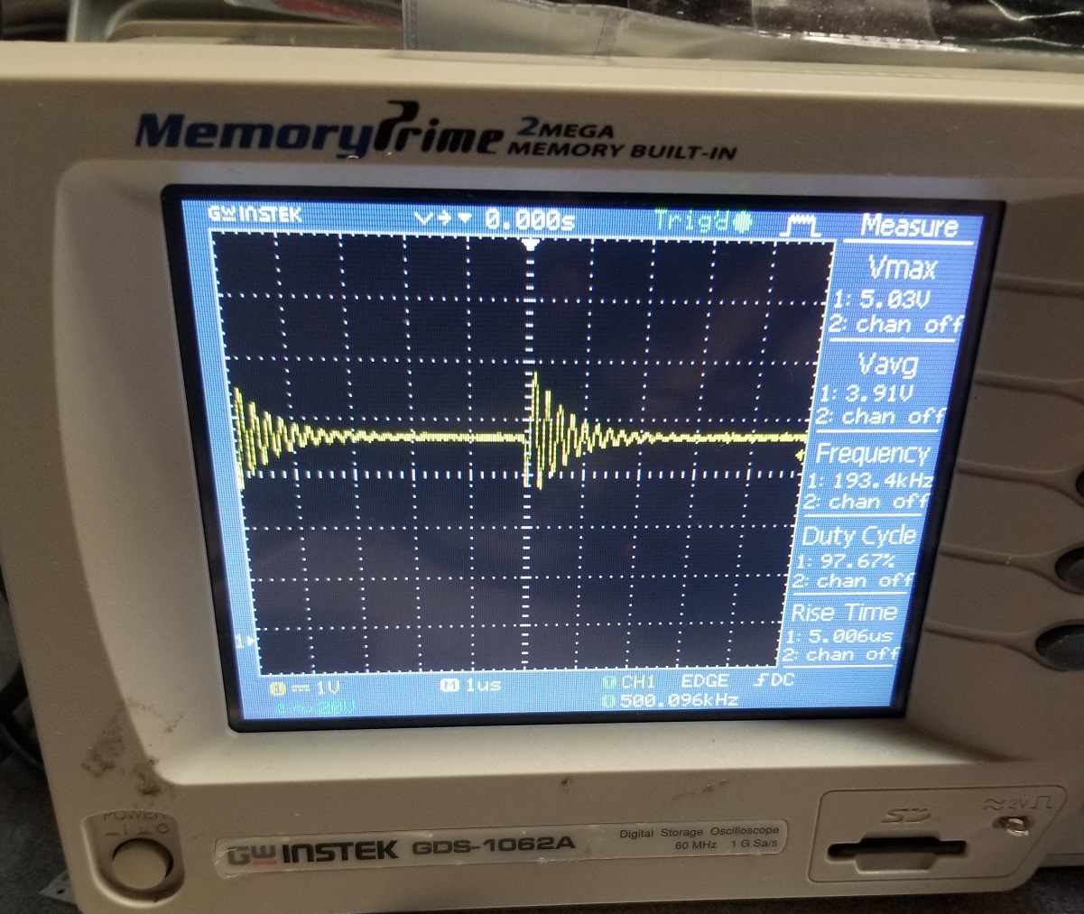
LoDRV pin waveform: