This thread has been locked.

If you have a related question, please click the "Ask a related question" button in the top right corner. The newly created question will be automatically linked to this question.

LMR14010A: LMR14010A

Part Number: LMR14010A

My design specification is: 5V input, 3.3V output, load typically in the range 350 to 400mA. Schematic as below.

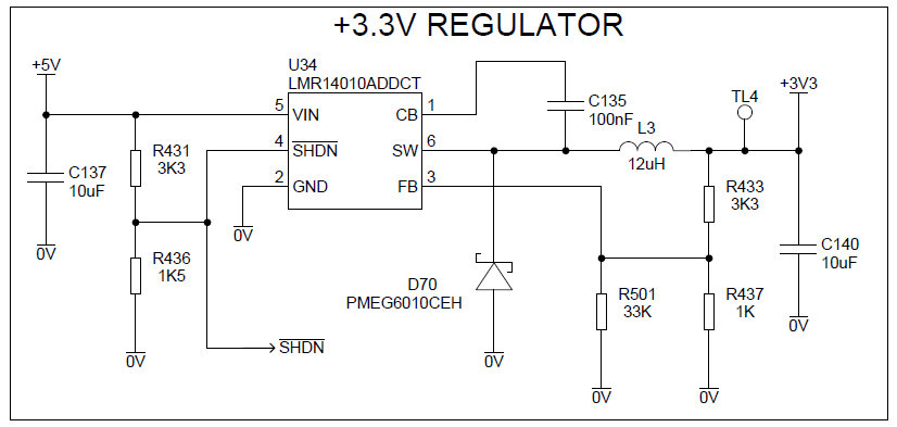
I have this working on a number of boards, no problem. However on one specific board, the SW output never starts switching; the output goes to about 2.70V. I'm powering the 5V input from a bench supply which shows input current of 197mA, so well inside the LMR14010's current / power rating.

Here are some turn-on waveforms. Yellow = 3V3 output, blue = SW output.

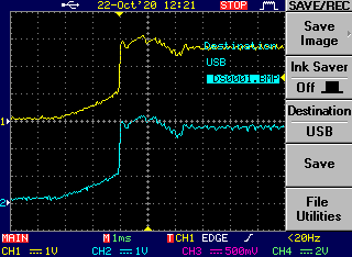
I've tried swapping the chip (twice) and the CB capacitor. I've also linked the 3V3 output from a good working board to 3V3 on the non-working (otherwise unpowered) board, so the good board is actually powering two loads. This works ok.

For reference, here are the corresponding waveforms on a good board (note the change of CH2 vertical scale).

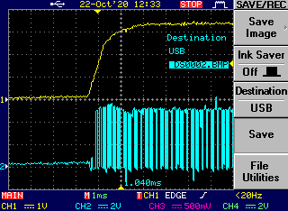
Although this only happens on one board, I'm concerned that I might have a marginal design. Any suggestions / help very welcome.

  • Hello

    I dont see anything too bad in your schematic.

    Did you use the Webench tool to design it?

    If not, can you use the Webench tool to check your component values.

    Try to raise the input voltage to 8V or 10V and see if it will start-up.

    Also, short out R431 to see if the EN divider is causing an issue.

    If possible, try to remove the load and test agian.

    It looks like your input supply is ramping up in some ms time frame; try "hot-plugging" the board to

    the power supply and see if it will start.

    Of course, you should be sure that all of the components are well soldered in and of the correct value.

    Send plots of your PCB layers and we will take a look at your layout.

    Thanks

  • Hello,

    Thank you for your prompt reply.

    I've found the problem. I replaced the inductor, and now all works well.

    It occurred to me that the initial slow rising voltage could be caused by a short-circuit or very low impedance inductor, such that the SW output connects directly to the 10uF output capacitor. I wasn't able to de-solder the inductor without destroying it, so I can't be certain, but I realised there's an issue with the specific inductor (Bourns SRR4528A -120M) with it's recommended footprint. If the part is placed 90° rotated, it shorts out the inductor. I suspect that's what happened and why other boards, with correctly placed inductor, work fine.

    FYI here's an extract from the Bourns data sheet: