This thread has been locked.

If you have a related question, please click the "Ask a related question" button in the top right corner. The newly created question will be automatically linked to this question.

PTH08T210W: Hiccup MODE

Part Number: PTH08T210W

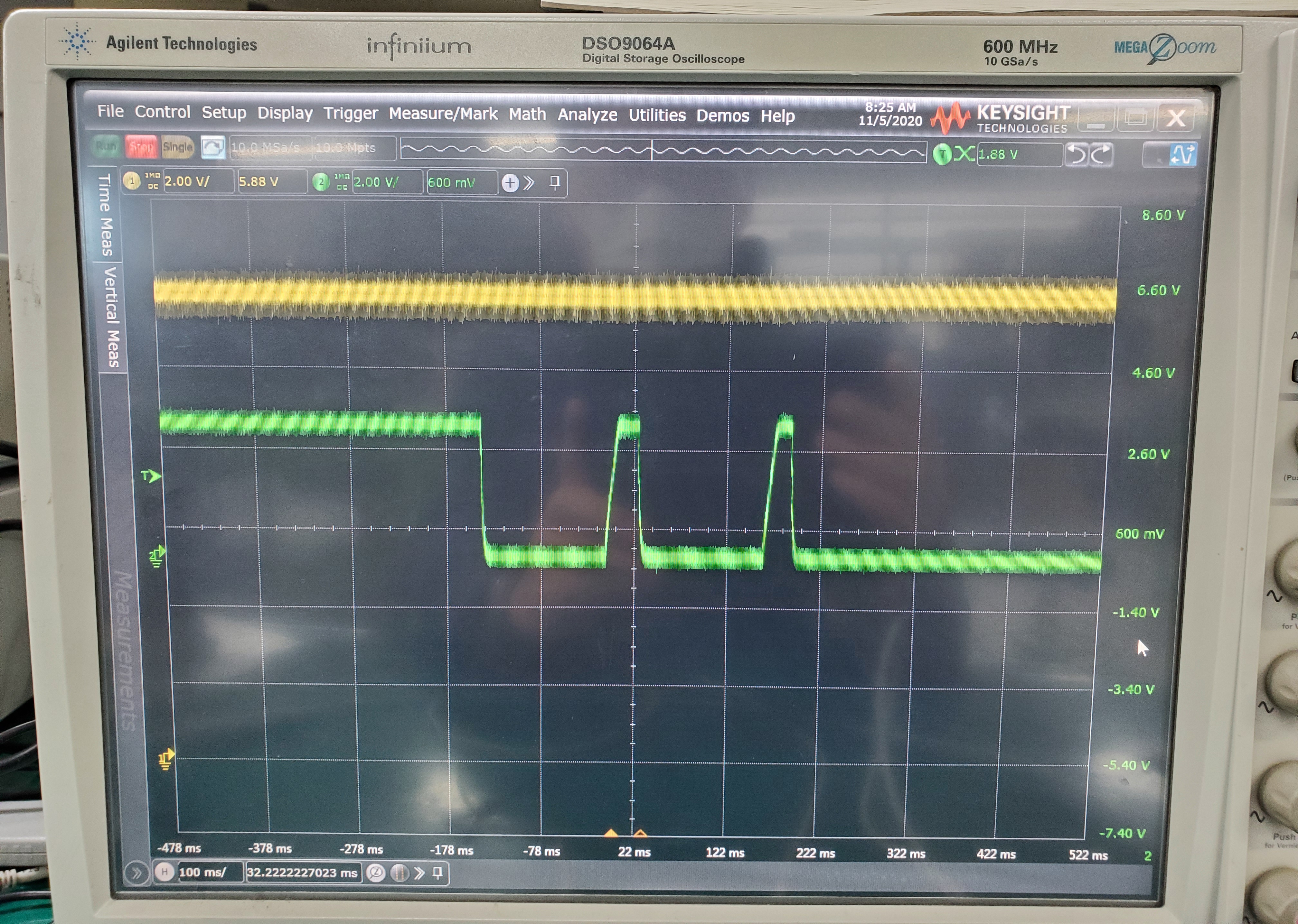
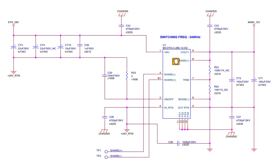
In my circuit, the output seems to go into hiccup mode.

The input moves slightly, but I don't know why it goes into hiccup mode.

There is almost no output load (300Ohm) and there is no actual overcurrent flow. Are there any similar cases?

  • Hi ,

    The part should not go into hiccup without cause. Can you please share more details, perhaps a schematic and oscilloscope waveforms?

    If you do not want to post here, please send through email to bsr-mvhc-support _at_ ti.com with the same subject as this thread ("PTH08T210W: Hiccup MODE").

    Thanks,
    Kris

  • Thank you for your attention Mr. Kris

    I attach the schematic and oscilloscope waveform.

    ch1 is input 12V and ch2 is 3V3 output.

    The situation is the same even if you connect a load resistance of 300 ohm or no load to the 3V3 signal.

    In the experiment, this phenomenon appears when the input voltage of the DC/DC converter is gradually lowered from 24V to 20V, and at that time 12V is stable.

    Thank You!

  • Hi ,

    Thanks for sharing.

    To confirm, prior to lowering the upstream 24V to 12V source, the PTH08T210W output is stable without issue, and only when you gradually lower the upstream input from 24V to 20V, then this hiccup occurs?

    Can you please capture the same waveform but include the upstream 24V input, and also the voltage at INH/UVLO pin as well? Please also add 12V offset to Ch1 12-V input and zoom in so that it is easier to see if there is some disturbance on the module input rail.

    It also appears that you have less than the minimum recommended input and output cap in your design (470uF min input, and 470uF min output as mentioned starting on datasheet p.12). It would be good to solder on additional bulk capacitors to both input and output (where C54 and C55 are) and see if the behavior changes. I do see that you have additional output cap after the diode controller, but the diode controller and sense resistor in line are isolating them from the PTH08T210W output.

    Also, where is the final Sense+/- lines being taken? I do not see where they terminate in the snippet. Are there additional circuits in line to the right of the snippet?

    Regards,
    Kris

  • INH/UVLO is controlled by the MCU on another board outside the board and works well.

    and  12V doesn't drop much.

    12V is created in isolated DC/DC Converter.

    If the Sys_28V is more than 24V in the circuit, there is no problem. If this power drops below 24V, 12V comes out well, but PTH08 works abnormally.

    Capacitance was tested with various capacities(47~2000uF), but the result is the same.

  • Thank you .

    Where is the final Sense+/- lines being taken? I do not see where they terminate in the snippet. Are there additional circuits in line to the right of the snippet?

    VIN and INH/UVLO look stable, so I would suspect SENSE+/- may be tripping OV or UV potentially. Can you probe SENSE+ during this event with zoomed in x-axis when VOUT first drops?

  • Thank you. Mr. Kris!
    SENSE+,SENSE- signals are taken from the back plane. And there is almost no voltage drop.

    But when I set RTT(R69) to 10K Ohm in my circuit, the problem was solved.

    Thank you very much for the help.

    Regard.