This thread has been locked.

If you have a related question, please click the "Ask a related question" button in the top right corner. The newly created question will be automatically linked to this question.

BQ40Z50-R1: 3.85V/Cell De-rating Application

Part Number: BQ40Z50-R1
Other Parts Discussed in Thread: GPCCHEM, BQSTUDIO,

Hi TI Team,

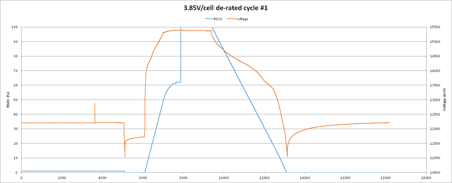
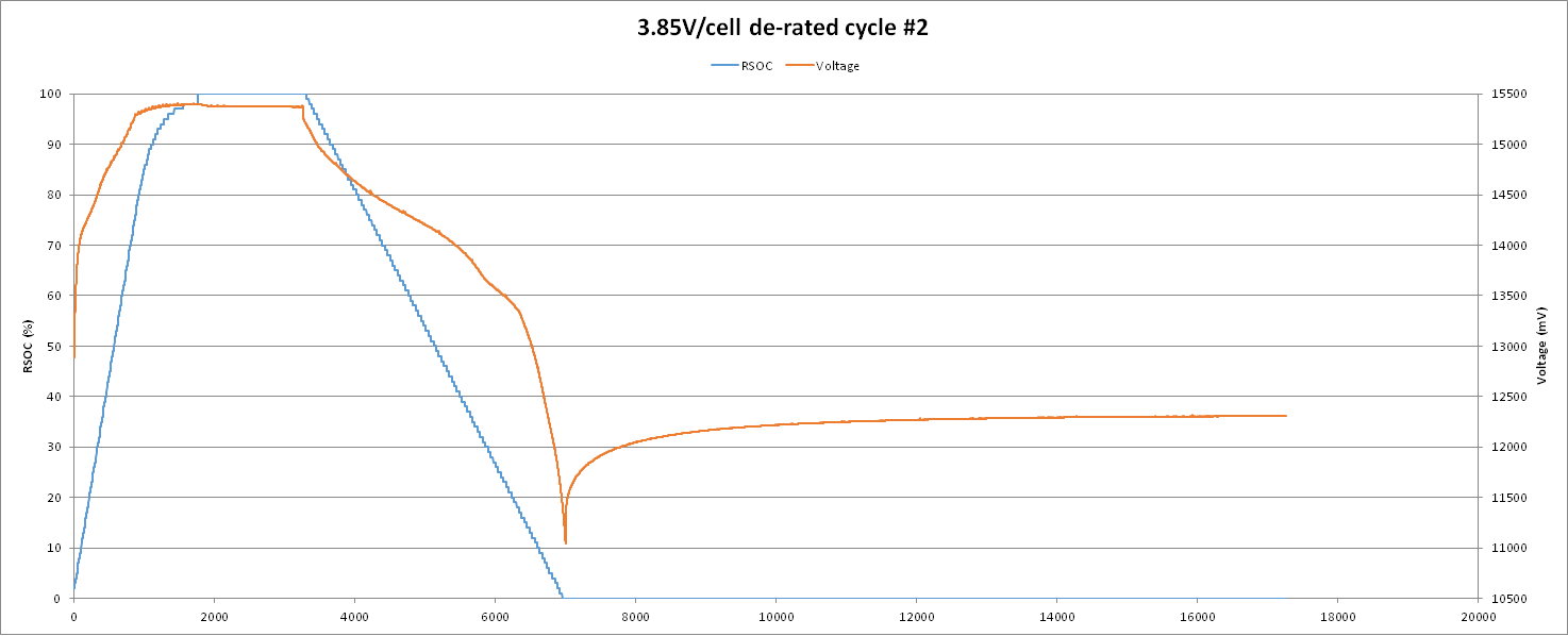
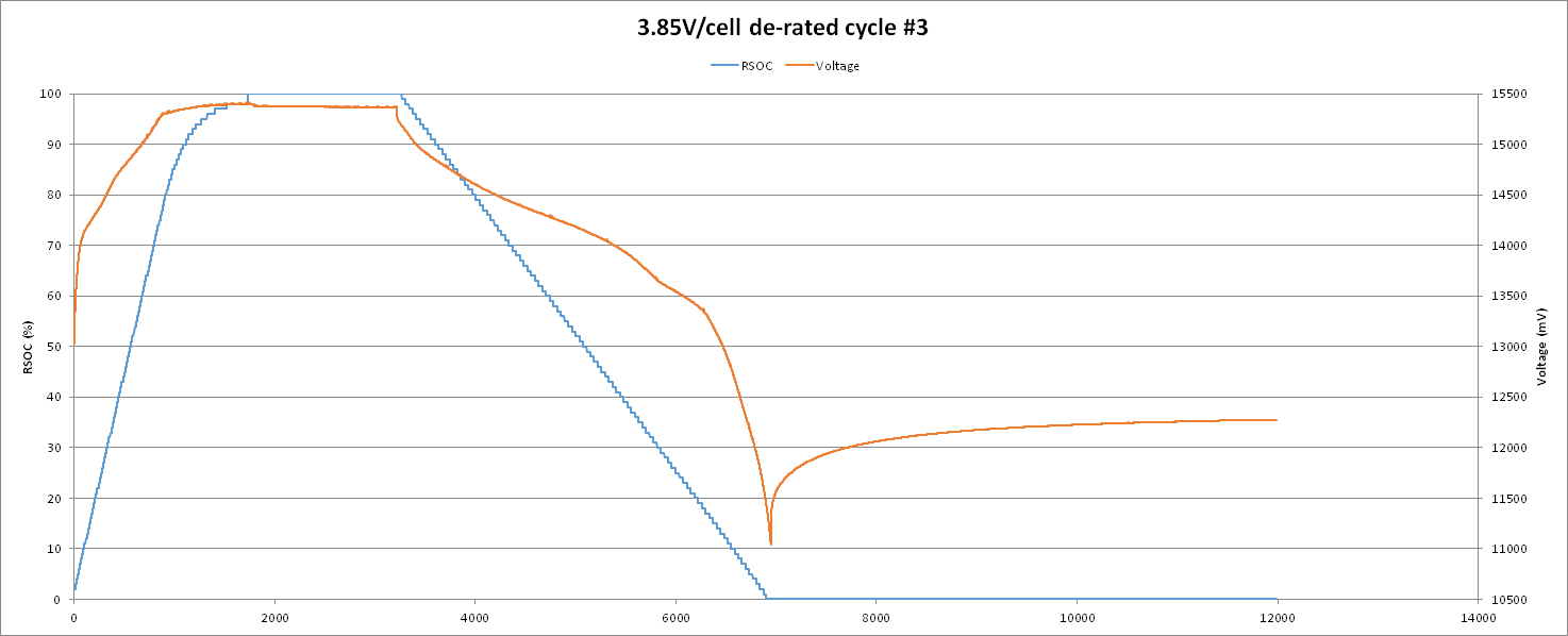
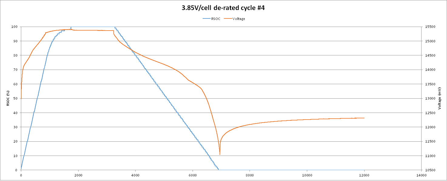
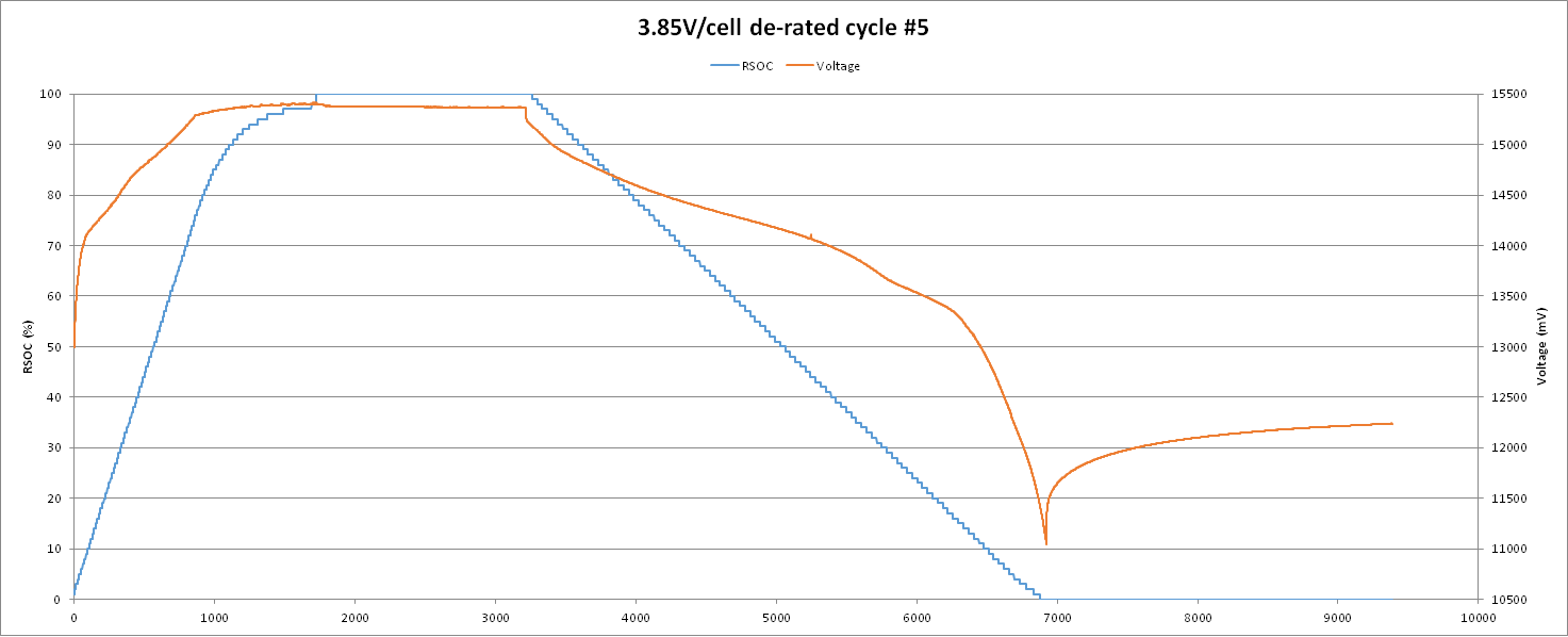
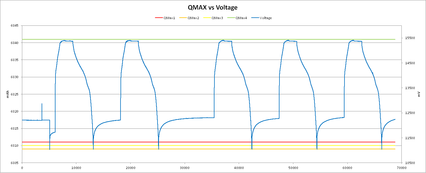
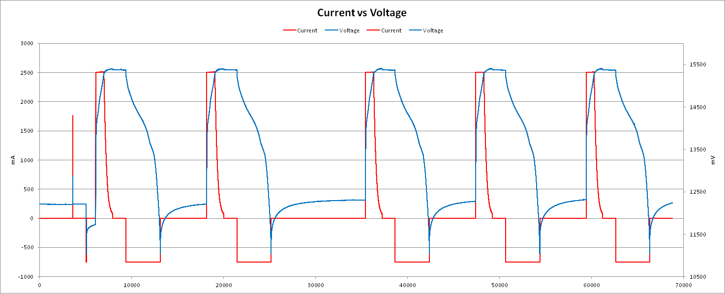
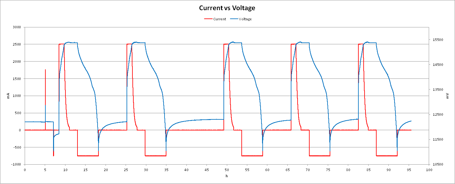
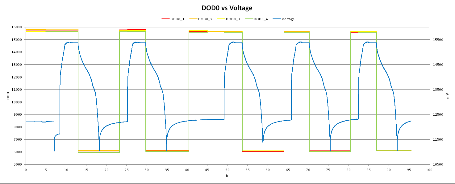
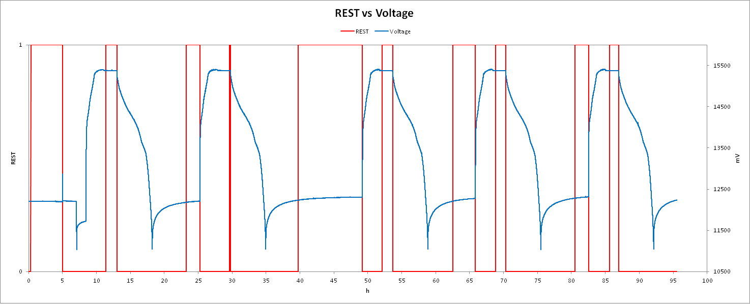
I have an application that requires charging voltage de-rated to 3.85V/cell. I tried to perform a learning cycle, but seems QMAX were not updated and FCC is updated about 1000mAh down to actual measured capacity. Can you please advise what to do for this case?

Also attached initial DF before learning cycle, last DF after learning cycle, and log data during learning cycle.

Thanks,

ZhihanInitial DF.gg.csvLast DF.gg.csvROM LOG.xlsx

  • Hello Zhihan,

    For the learning cycle we recommend cycling the full voltage range of the battery according to the manufacturer, then after the learning cycle you can reduce the voltage range to match your application.

    We need a 90% change in DOD during the learning cycle which you are probably not reaching if you are charging to 3.85V.

    Sincerely,

    Wyatt Keller

  • Hi Wyatt Keller,

    Thank you for your recommendation!

    I tried to use 4.2V/cell for learning cycle, then use 3.85V/cell for another 2 cycles after the learning cycle. And I found that the update status became 0x05 during first post-charge relax period (was 0x04 before). However, update status remains 0x05 since then, which seems not following the learning cycle procedures. Can you please advise what to do with it?

    Also attached the log data during cycles.ROM LOG 4.2V Learning.xlsx

    Thanks,

    Zhihan

  • Hello Zhihan,

    We usually follow the SLUA903 app note for learning cycle: e2echina.ti.com/.../0827.7367.Achieving-the-Successful-Learning-Cycle.pdf

    Watch for the currents in discharge (c/5 to c/10) and the 2 DOD points which need to be more than 90% of the design capacity.

    Which chem ID are you using? Can you share the GPCCHEM report?

    Sincerely,

    Wyatt Keller

  • Hi Wyatt Keller,

    Thank you for your reply!

    I was following SLUA777 to conduct the learning. It looks like the procedures are the same?

    The "update status" behaviors are different in the 2 documents. However, by checking the doc you shared, update status in my case is still not as expected, it remains 0x05 during post-discharge rest period and afterwards.

    The cell I'm using is LG's INR18650F1L (min 3250mAh, typ 3350mAh @ 4.2V), with 4S2P configuration. 3.85V/cell will be the actual application. And in the log data, 3.85V/cell charging cycles after 4.2V/cell cycle was just to verify if FG works ok after 4.2V learning cycles. Since there is something wrong with 4.2V learning cycle, so I guess we can ignore the 3.85V cycles.

    Design capacity is set to 3900mAh, which is the measured capacity with 3.85V de-rating. So using 4.2V learning, 90% DOD of design capacity is certainly exceeded. Charge current was ~3350mA (0.5C of 6700mAh @ 4.2V), and discharge current was ~ 1300mA (0.2C of 6700mAh @ 4.2V).

    The chem id is 1762. I'm not sure about the GPCCHEM report part. Can you please explain a little bit?

    Thanks,

    Zhihan

  • Hello Zhihan,

    The document I linked contains the requirements for discharge and the bits that indicate if a OCV has been taken, along with other information that may be helpful like battery rest times between cycles. Before de-rating the voltage the learning cycle must be fully completed and 2 OCV measurements are needed.

    If you are using the direct battery that matches you don't need to use the GPCCHEM tool, but if there's not an exact match then you should follow the document on the GPCCHEM page to submit a relax - discharge - relax log to find the chem ID.

    Sincerely,

    Wyatt Keller 

  • Hi Wyatt Keller,

    Below is how I did my learning cycles:

    1. Program the chem id 1762.

    2. Enable fuel gauge then full reset.

    3. Discharge to 11V using 1.3A.

    4. Rest 5 hours.

    5. Charge to 16.8V using 3.35A down to 80mA.

    6. Rest 2 hours.

    7. Discharge to 11V using 1.3A.

    8. Rest 5 hours.

    9. Charge to 16.8V using 3.35A down to 80mA.

    10. Rest 2 hours.

    11. Discharge to 11V using 1.3A.

    12. Rest 5 hours.

    Update status changed from 0x04 to 0x05 automatically during step 6.

    Please advise if the whole process was correct.

    Thanks,

    Zhihan

  • Hello Zhihan,

    That looks correct to me, make sure any protections you have are also turned off.

    Can you perform the relax - discharge - relax and check to make sure the chem ID is matching, then we can verify that's not the issue.

    Make sure you program all the other parameters like design capacity and taper currents/ quit current as well.

    Sincerely,

    Wyatt Keller

  • Hi Wyatt Keller,

    Thanks for checking on my procedures!

    Protections are enabled but I adjusted thresholds not to interrupt the learning cycle. (e.g. COV = 4.35V). I guess this would be ok?

    Can you explain a little bit more about "relax - discharge - relax" you mentioned? For example, right now my battery is fully discharged because of the learning cycle. So I guess will need to fully charge (16.8V) the battery first then rest for 2 hours then discharge using 0.2C then rest for 5 hours? After that, how can I verify if the chem ID is matching? Please kindly advise.

    All other parameters were programmed before learning cycle. Design capacity is 3900mAh (at 3.85V/cell derating), taper current is 100mA (= 50mA/cell), quit current is using default value.

    Thanks,

    Zhihan

  • Hi Zhihan,

    GPCCHEM tool will provide you with a chemID and the error deviation.

    Best regards,

  • Hi Nick Brylski,

    I'm checking the GPCCHEM and planning to perform this test. Before running the test, I have several questions about the test setup. Please kindly advise.

    1. This test will be done on battery pack level not cell level right?

    2. Do I need to replace new cells for the test? Currently I've already run 11 cycle on my pack, will this be a problem?

    3. Should I run the test using cell datasheet's condition, or using my application's condition (e.g. 3.85V/cell charging)?

    4. I will be using MACCOR to run the cycles for the test. Meanwhile, bqStudio will be used as well for logging. So I'm wondering which data should I upload, MACCOR or bqStudio?

    Thank you in advance,

    Zhihan

  • Hello Zhihan,

    It can be done on either, we usually recommend doing it on a single cell to reduce pack trace resistance interference.

    No you don't need to replace the pack if it has 11 cycles.

    It should be performed by the pack manufacturers datasheet because we use that to generate the chem ID.

    For the GPCCHEM you can edit the bqstudio log to submit to the tool. It is explained in the document on the GPCCHEM page.

    Sincerely,

    Wyatt Keller

  • Hi Wyatt Keller,

    Thank you for your answers!

    Just want to quick confirm that "pack manufacturers datasheet" means the designed spec for the pack right? For example in this case, we would want to de-rate the battery to 3.85V/cell. So we will be using 3.85V charging instead of std 4.2V from cell datasheet right?

    Best Regards,

    Zhihan

  • Hi Wyatt Keller,

    My co-worker helped and submitted GPC package. And report said there is no existing chem ID matching. So I'm wondering if it is possible to have a customized chem ID for our application?

    Also attached GPC Package and report. Please advise if anything else we need to do.

    Thanks,

    Zhihan

    4214.GPCPackaged.zip4745.GPCPackaged-report.zip

  • Hello Zhihan,

    Sorry for the confusion, it should be based on the cell datasheet, not the pack. When we characterize the cell there could be many packs with different voltage levels for the same cell we characterize.

    I checked your log, it looks like you submitted a charge-relax-discharge-relax-charge log.

    Try trimming the data to just the relax-discharge-relax sections of your log and submit again.

    Sincerely,

    Wyatt Keller

  • Hi Wyatt Keller,

    Thank you for checking the log!

    There is additional chg should be removed. I'm check the guide SLVA725A, found chg-relax-dsg-relax is needed. So just want to double confirm with you, i will trim to chg-relax-dsg-relax or relax-dsg-relax that you just mentioned?

    Also, my real application would be derating to 3.85V/cell charging which is greatly lower than cell manuf. specified. So why I should run the cycle based on cell manuf. ? I'm still a little bit confused on that. Please kindly advise.

    Regards,

    Zhihan

  • Hello Zhihan,

    Yes just submit the relax-discharge-relax portion.

    Once you have completed the learning cycle (the step after selecting the chemistry ID) then you can reduce the battery voltage for your application.

    Refer to SLUA903 for information on the learning cycle.

    Sincerely,

    Wyatt Keller

  • Hi Wyatt Keller,

    Thank you for clarifying!

    I uploaded trimmed data but still got error report. Please kindly review attached package and report.

    8831.GPCPackaged.zip7827.GPCPackaged-report.zip

    Just want to summarize the discussion a little to make myself clear what to do since we really had a long discussion here. Please kindly correct me if following understanding is wrong.

    First perform a chg-relax-dsg-relax cycle using cell spec condition to find out proper chem ID.

    Then use chem ID and perform learning cycle using 4.2V charge.

    If learning cycle is successful, then we can use 3.85V de-rating as application.

    Thanks,

    Zach

  • Hello Zhihan,

    Can you perform the process on a single cell? Also what is your max charge voltage in the cycle? It should be to the battery specs also, not the de-rated value.

    Yes that's the correct procedure for preparing the gauge.

    Sincerely,

    Wyatt Keller

  • Hi Wyatt Keller,

    The data I shared was using 3.85V de-rating. So we started over the whole process last week with re-selecting the chem ID. The new ID is 2155 for INR18650F1L cell. We did it on the battery pack level, using cell spec condition to do the cycle.

    Then we used the new ID for learning cycle. However, we still find that learning process failed. Update status was initially 0x04. Then changed to 0x05 at the first cycle but remain unchanged for the rest 2 cycles.

    Please kindly advise what to do with this situation.

    Thanks,

    Zhihan

  • Hello Zhihan,

    Can you share the .gg before and after the learning cycle along with the logs so we can take a look at them for debug, we cannot say much without the data.

    Sincerely,

    Wyatt Keller

  • Hi Wyatt Keller,

    Thanks for the reminder! I almost forgot. Please kindly review attached zip file. Log data and some exported GG files during the learning cycle are all included.

    Thanks,

    Zhihan

    S617 Chem ID2155.zip

  • Hello Zhihan,

    I see in the log the discharge current is more than C/5 (C = design capacity, max discharge for learning cycle for your battery is 780mA) I would consider setting it at 700mA.

    The information regarding the required currents with thresholds programmed to the gauge are outlined in SLUA903.

    Your cycles look good, you were able to get a Qmax which shows you cycled the batteries 90% DOD, but the current must be within C/5 and C/10 for Ra updates during the learning cycle.

    Sincerely,

    Wyatt Keller

  • Hi Wyatt Keller,

    Thanks for reviewing! We will try on 700mA discharge.

    I'm just wondering since we are using standard 4.2V/cell charging for learning cycle, so why C /= nominal capacity (6500mAh), but = design capacity (3900mAh)?

    Thanks,

    Zhihan

  • Hello Zhihan,

    I'm not sure what you mean, in your .gg file design capacity is 3900mAh, so C = 3900mA. Your max discharge rate for a learning cycle should be 3900/5 = 780mA.

    Sincerely,

    Wyatt Keller

  • Hi Wyatt Keller,

    I mean design capacity = 3900mAh is measured based on 3.85V de-rating. However, nominal capacity using standard 4.2V is 6500mAh. (F1L cell has nominal 3250mAh min capacity, with standard 4.2V, battery pack is 4S2P configuration.)

    And since for learning cycle, we are using 4.2V, so I was just wondering why discharge current is based on design capacity not nominal capacity.

    Thanks,

    Zhihan

  • Hello Zhihan,

    The design capacity does not need to be changed unless you are seeing SOC jumps after the learning cycle. The design capacity should be set to the cell manufacturers value for learning (if it's 2P then it's 2 times the manufacturers value, etc)

    During the learning cycle the capacity is not de-rated because you have the full voltage range.

    Sincerely,

    Wyatt Keller

  • Hi Wyatt Keller,

    Let me summarize it a little bit. Please correct if I'm wrong.

    For learning cycle, we should set design capacity to be based on cell manufacturer. After leaning cycle is successful, we can use 3.85V de-rating which is the application requirement.

    So, another question is, after learning cycle is successful which would be expected since there are basically no de-rating, and before we actually start using 3.85V application, do we need to decrease design capacity accordingly? Because otherwise, full charge capacity is expected to be greatly decreased due to the de-rating, and cause SOH to be greatly decreased.

    And if we need to decrease design capacity for real application, do we need to perform another one or two calibration cycles based on 3.85V de-rating? Also except design capacity, another parameter needs to be changed for 3.85V de-rating? Additionally, from SLUA903, design capacity is set before learning cycle, so if we change design capacity, will that invalidate the learning cycle we did on 4.2V which is cell manufacturer condition?

    And if 4.2V learning cycle is successful, however 3.85V application doesn't work out, for example, max error increases, full charge capacity is deviated greatly from actually measured capacity, or SOC jumps hugely, or else. What would you recommend to resolve 3.85V de-rating application issue when use 40z50-r1?

    Please kindly advise!

    Thanks,

    Zhihan

  • Hello Zhihan,

    The gauge learns the Qmax and Ra values for the gauge during the learning cycle, when you decrease the max voltage or terminate voltage you will need to adjust the parameters in the gauge (FC threshold, or if you meet the VCT criteria already) this will let the gauge know where the max and min values are.

    The gauge should adjust according to the bounds you program for terminate voltage and full charge termination.

    VCT: Valid Charge Termination

    FC: Full Charge

    Sincerely,

    Wyatt Keller

  • Hi Wyatt Keller,

    Thanks for the update! However, I'm getting more and more confused.

    So we are having at 4S2P battery application that requires only 3.85V/cell de-rated charging and operation voltage from 2.8V/cell ~ 3.85V/cell. The lithium ion cell we use according to its datasheet has standard operation voltage from 2.5V ~ 4.2V. Based on our measurement, battery capacity under 2.8V ~ 3.85V/cell is about 3900mAh and nominal will be 6500mAh (min) per cell datasheet. Charge Term Taper Current we will just use cell datasheet condition.

    Per your suggest for learning cycle, we should set cycle condition for learning cycle based on cell datasheet not application. Plus, design capacity is set to nominal capacity from datasheet. So with 6500mAh for design capacity, when we actually apply de-rated application, FCC will significantly lower than design capacity that results in significantly low SOH, ~60%, which I don't think that will make sense since we are just using very little portion of the cell not that the cell is already very aged.

    Plus I assume I should set Term Voltage to 10V not 11.2V?

    Also you mentioned VCT and FC. Current GG uses default FC set condition which is VCT. And VCT is affected by ChargingVoltage(). ChargingVoltage() is reflected under Advanced Charge Algorithm for T1~T2, T2~T5, T5~T6, T6~T3, T3~T4. So what voltage should we set for ChargingVoltage(), 4.2V or 3.85V?

    If we set everything in GG based on cell datasheet, how is this GG helpful to our real application even if learning cycle is successful? Because I assume learning cycle is for IC to learn real application by cycling use real situation and GG is customized for real application as well. Please kindly advise.

    Also can you please kindly review GG again and advise all the parameters needs to be adjusted for my case? I don't prefer to repeat cycles again and again with one or two parameters adjusted every time.

    At last, is that possible to request a customized chem ID for my case?

    Thanks,

    Zhihan

    1S617 ID2155.gg.csv

  • Hello Zhihan,

    I would try GPCCHEM as the first premises.

    In order for the learning cycle to be successful, there are multiple steps you have to follow. We have online applications guides for this. I would try to look at those.

    If you can provide us a log file of your learning cycle, we can debug this further.

    Thanks!

  • Hi Kang Kang,

    With all my respect, would you please kindly and carefully review all previous conversations and attached files? Then tell me what to do please?

    I've already gone through GPCCHEM, learning cycles as suggested, and provided log data. And got your feedback which just made me even more confused. So I raised more questions. Now you tell me to start all over again and provide data again?

    Or will that just be easier to tell me that bq40z50-r1 is not able to be used for 3.85V/cell de-rated application?

    Sincerely,

    Zhihan

  • Hi Zhihan,

    Please provide the data we requested and we will continue looking into this

    Thanks,

  • Hi Nick Brylski,

    We have re-run the learning cycle based on cell manufacturer specification (voltage range, 0.2C discharge, design capacity and term voltage). The learning cycle looks good. Then we changed design capacity and term voltage to application specification, and have run additional 6 cycles based on application specification. Most registers looks good expect CELL1,2,3,4 QMAX. The QMAX of the cells were not updated. Can you please  kindly advise what adjustment would be needed?

    I'd like to upload my data but the file sizes are way too large. Is there any other way to share those data to you?

    Thanks,

    Zhihan

  • Hello Zhihan,

    Are you having an issue with SOC jumping? Qmax will be updated as the batteries age and conditions change.

    If there are not issues with gauging the Qmax values should be ok.

    Sincerely,

    Wyatt Keller

  • Hi Wyatt Keller,

    For QMAX, based on the observation on my other applications, it will change more or less after each chg or dsg cycle. However in this case, it doesn't change even 1mAh, so I'm not sure if this would be an issue for aging expectation.

    For SOC jump, It looks like, more or less, during charging, SOC jumps near ~98%. Except in 1st cycle, it jumps from 60% to 100%. In the rest 4 cycles, SOC jumps from 98% to 100%. Please see below figures as summary. Also attached gg files (before learning, after learning done, and adjusted for 3.85V cycles which is after learning is done). Please kindly review and advise.

    Thanks,

    Zhihan

    Before learning.gg.csv

    learning complete.gg.csv

    Adjusted for 3.85V cycle.gg.csv

  • It looks like the figures were not uploaded correctly. So upload again. Please kindly review.

  • Hello Zhihan,

    The later cycles look good, a small jump of 2% near EOC (end of charge) would not be very worrisome.

    You can check if Qmax is being updated by enabling lifetime data and checking after you cycling the batteries by at least 37% and include the relaxes.

    Sincerely,

    Wyatt Keller

  • Hi Wyatt Keller,

    I checked the data log, MfgStat = 0x1F8 all over the time. So I believe lifetime is enabled during all 5 cycles. Below figure is comparing QMAX to Voltage. Not sure if this is reflecting the QMAX lifetime you mentioned. It looks that QMAX is just flat, no any changes.

    Also attach Current vs Voltage and RSOC vs Voltage as references to show the state of the battery.

    Please kindly review and advise any other data you'd like to review. Do you think we should run another e.g. 5 or 10 cycles to verify if QMAX will be updated?

    Thanks,

    Zhihan

  • Hello Zhihan,

    Do you have IT enabled for all the tests? If the learning cycle was completed before the start of the logs you showed then the RSOC should be tracking.

    Qmax will not update if the rest between cycles is not long enough (which is what it looks like from the graphs) There needs to be 5hr rest or check the bits to see if an OCV was taken.

    If no OCV was taken the Qmax won't update.

    Sincerely,

    Wyatt Keller

  • Hi Wyatt Keller,

    Yes,  IT is enabled for learning cycles and application cycles. (ITEN bit of LStatus was set all the time.)

    Sorry for misleading. I didn't adjust x-axis because there seems some max limit for ElapsedTime from log data. Log interval was 5s. Below are the correct ones. When we did the cycle, we set 2 hour rest after charge and 5 hour after discharge. So I think the rest time probably is not the problem.

    BTW, is there any way to increase ElapsedTime limit in the log data? I found in my data, max value is nearly 60000s then it will start over from 0s.

    Thanks,

    Zhihan

  • Hello Zhihan,

    Were the DOD values changing as well? Were there OCV's being taken? If the OCV measurements are being taken Qmax will not update. You can check in the bit registers if an OCV was taken and if it qualified for Qmax update.

    Sincerely,

    Wyatt Keller

  • Hi Wyatt Keller,

    It looks to me, DOD were changing. But I'm not quite sure how to interpret these values. Can you please a little bit? Also please kindly review below figure showing DOD0 values.

    I also checked IT Status, REST bit was set during rest period. Please see below figures showing REST bit status.

    Thanks,

    Zhihan

  • Hello Zhihan,

    Can you share the log file you are making the graphs with? Did the Qmax flag toggle at each point?

    The DOD represents the value in the chem ID where the OCV corresponds to that DOD, it's just measured out of 2^14 instead of 0 to 1 as normal.

    Sincerely,

    Wyatt Keller

  • Hi Wyatt Keller,

    Thanks for your explanation!

    I would love to share my log data. However, the files are nearly 45MB so that I can't upload them here. Do you have a different way accept these large files?

    QMAX bit is 0 all the time.

    Thanks,

    Zhihan

  • Hello Zhihan,

    Can you trim the log so there's only one charge/discharge? Or parse so there's less data points?

    If Qmax never toggles there's something blocking a Qmax update, I would check the Qmax disqualifications in the TRM and make sure you're not violating any of the conditions.

    Sincerely,

    Wyatt Keller

  • Hi Wyatt Keller,

    I trimmed my data which includes the 4th de-rated cycle only. Please kindly review and advise. And let me know if you need the other 4 cycles trimmed data.

    Thanks,

    Zhihan

    application cycle log 4 TRIMED.xlsx

  • Hello Zhihan,

    It looks like it's being disqualified because of the OCVFR flag, is this still chemistry ID 2155? It looks like the gauge thinks it's always in the flat region.

    Can you try disabling the OCVFR in IT gauging configuration to see if Qmax will update after that's changed? Just do 1 cycle so we can confirm if that's the issue.

    Sincerely,

    Wyatt Keller

  • Hi Wyatt Keller,

    Yes, chem id is still 2155. We didn't change that after learning cycle.

    And we will try another cycle by disabling OCVFR.

    For OCVFR, I'm a little bit confused. From the log data, I found OCVFR bit in IT Status in mostly cleared. Does that mean battery is never in flat region?

    Thanks,

    Zach

  • Hello Zhihan,

    It looked like a majority of the cycle sent the OCVFR was set, for the other cycles were you not seeing that?

    Yes, the OCVFR flag is set when you're in the flat region and relax mode.

    Sincerely,

    Wyatt Keller

  • Hi Wyatt Keller,

    I mean from the log data, by checking LT Status, I found most of the time, OCVFR is not set (highest 4 bits are mostly 0x0). May be I was wrong. Please correct me if so.

    Also attach trimmed log data for you to review, including learning cycles and application cycles.

    We are still running the cycle with OCVFR disabled.

    Thanks,

    Zhihan

    4.2V learning cycle trimmed.xlsx3.85V application log trimed.xlsx