This thread has been locked.

If you have a related question, please click the "Ask a related question" button in the top right corner. The newly created question will be automatically linked to this question.

TPS2121: Help with TPS2121 for Automatic Switchover Between Two 5-V Supplies

Part Number: TPS2121
Other Parts Discussed in Thread: TIDA-01638

Good day Colleagues,

Could you help the customer with the TPS2121 for the Automatic Switchover Between Two 5-V Supplies?

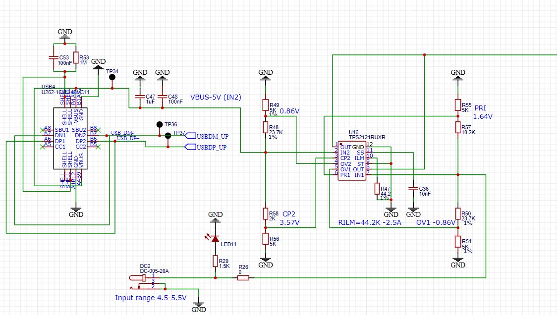
IN1 - is a primary +5V input. IN2 - secondary +5V input. Both inputs can be connected simultaneously.

The TPS2121 should use the primary (IN1 +5V) input to the output even if the secondary (IN2 +5V) is connected. And switch to the IN2 if IN1 was disconnected.

the task is similar to what the datasheet on page 27 (pic 10-12) and the TIDA-01638 (

https://www.ti.com/tool/TIDA-01638) design used for but for +5V in customer's case.

Could you help to find an optimum resistors values for pins PR1, ST, OV1 and OV2? What ref voltage customer should use for the SP2 pin?

Thank you, Mikhail

  • Hi Mikhail,

    "Optimum resistor" values are subjective and depend on the application and the switchover behavior that is used. I highly recommend using resistors in the 10-100 Kohm range to set the voltage values at OV1,OV2,PR1 and CP2.

    Looking at the TIDA design, this is a seamless switchover for backup power which means that the application needs to use fast switchover. FOR this PR1 and CP2 have to be bigger than Vref (1.06V typ) at the time of switchover. The next consideration is at what voltage does the system need to switch from one voltage to another? Once again this is application dependent.

    Let us consider the switchover voltage to be 4V on IN1. At this input, the voltage on the CP2 pin must be larger than the PR1 pin. So a resistor divider network that results in 2V on PR1 when VIN1=2V on PR1 and 2.1V when VIN2=5V on CP2 would result in fast switchover.

    As you can see, the final design is dependent on a lot of factors. A good starting point might be to take a look at the TPS2121EVM as we have a divider network set up for 5V switching. You can find it here: https://www.ti.com/tool/TPS2121EVM-023 

  • Hi Team !

    Thanks for the quick reply!

    We are using TPS2121 in one of our design and the circuit connection is as shown below.
    Is there anything wrong in the circuit connection.
     The operating condition we are looking at is that when both EXT_5V and VBUS is present, EXT_5V should be switched to the output when only VBUS is present then we want the VBUS to be switched to the output.
    And EXT_5V should be switched to the output when VBUS is not present.
    Now we have switching TPS2121 as shown below
    BR, Alexander
  • Hi Alexander,

    Can you please describe what your intent is with TPS2121?

    Do you want fast switchover or is slow switching acceptable? At what voltage would you like the switchover to take place at?

    Right now, I am seeing that PR1 is at 1.644V and CP2 is at 3.57V but IN2 has to drop to 2.3V (which is under the UV threshold) for switching to occur. THis is incorrect operation.

    Please provide a scopeshot that describes PR1, CP2, VOUT and ST that shows the event above.

    Secondly what is the load current in the situation you shared above?