Hi Sir,
Would you pls help for bq24075T schematic questions as below? thanks.
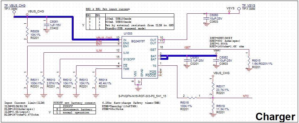
VIN: VBUS_CHG(5V), from USB
VBAT: 560mA, 1C Li-ion Polymer Cell, typ. 3.7V max 4.2V
Input Current set: 600mA
Output Current set: 556mA
Q:
- EN2 connect to VBUS_CHG through 10Kohms, is it means input current from USB will control by ILIM?
- EN1 connect to GND through 100Kohms, is it make sense?
- SYSOFF connect to GND through10Kohms, is it make sense if we will not disconnect VBAT?
- We will not use OUT, CE connect to GND through 10kohms is fine?
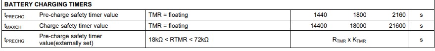
- For TMR pin, spec describe "6.25hour fast-charge safety timer", what means 6.25 hrs? Can we change 6.25hrs with others resistor value(d/s shows 46.4K)
- If not use PGOOD and CHG, need connect to GND or floating?是否能直接float?
- Input and Output capacitors have suggest value?
- OUT pin not used, connect it to GND through10uF, is it fine?
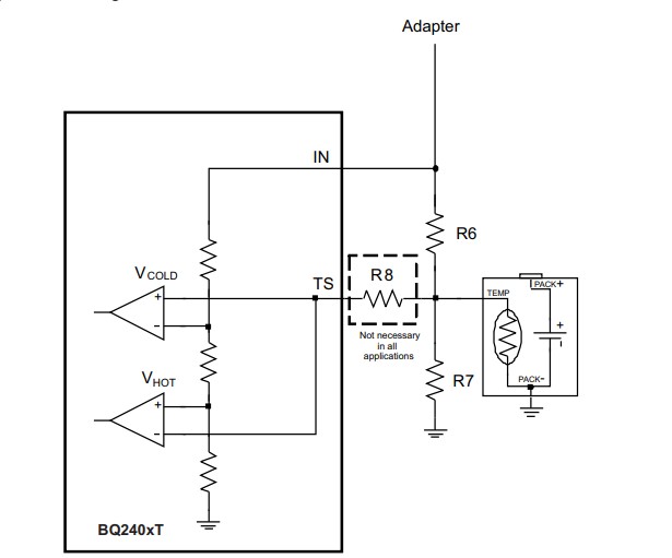
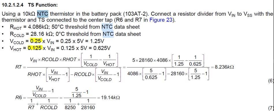
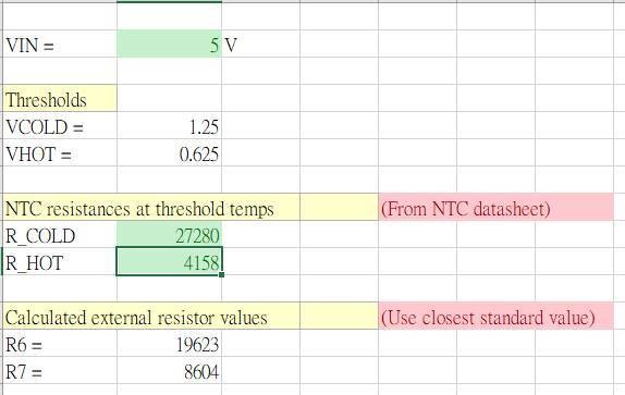
- TS pin, VCOLD and VHOT 0.25 and 0.15 are fix value?(as below fig.)
0 and 50 degree is fixed value or it can change by customer?
According NTC (10K, B value 3435)spec in 0 degree and 50 degree calculate as below formula, 19.6K and 8.66K are make sense?
Thanks, Ian.