This thread has been locked.

If you have a related question, please click the "Ask a related question" button in the top right corner. The newly created question will be automatically linked to this question.

TL1431-SP: Delay circuit

Part Number: TL1431-SP
Other Parts Discussed in Thread: TL1431, , TL431

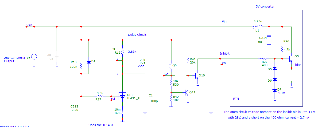
Question about using the TL1431 as a delay circuit in the comparator mode. This would be open loop mode with a resistor to the ref pin and capacitor to ground. The ref input through the resistor and the cathode (through resistor) are supplied from the same power supply (28V), but the reference voltage lags due to the RC time constant when the 28v starts up.  When the 28V supply ramps up, the voltage on the reference pin will ramp up much slower and when the reference crosses the threshold, the cathode will go "low" switching a PNP transistor. The circuit is similar to one shown in the SLV987A app note. The data sheet shows Ii(ref) (-55C to 125C) to be 5uA max, so the resistor value in the RC network on the reference input is selected to provide  >> 5 uA.   By the time the voltage on the ref input gets to about 2.5V, the 28V is fully up and the cathode resistor was selected to provide the recommended Ika of at least 1mA. I have not seen a specific application for a xx431 as delay circuit so would like to know if there are any issues to be aware of.  In the app note SLVA987A, it states that Vka(low) can vary per device and depends on Vref, Ika, and Iref.  Is there a safe maximum value for Vka(low) that can be used for design purposes? Figures 3 and 4 on the TL1431 data sheet show Ika vs Vka, with Vka max at about 2.5V (at 25C).

  • Hi Mark,

    Can you post a schematic to be sure your circuit description is being interpreted correctly? Besides considering the minimum current requirements, also make sure not to exceed the maximum recommended cathode current or the Abs Max reference input current. I will look into your question concerning the max value of Vka(low). 

    Thank you,

    Sarah

  • Diagram included.  28V source on the left. TL431 delay circuit in the middle, input circuit for inhibit function on DC/DC converter on right. Not all component values are finalized yet. I only have a spice model for the TI431.  Circuit will use the TL1431-SP. As the 28V supply (on the left) ramps up, want to hold the 5V converter disabled. When the 28V ramps up it directly feeds Q10 turning it on, inhibiting the 5V supply. This happens at very low voltage. After delay (R13, C213 time constant) voltage passes the threshold and cathode goes "low" turning Q6 ON, and Q11 ON, which turns Q10 off, releasing the inhibit.  As the 28V is rising, Iref will be met when the voltage gets to about 6V. By the time the voltage on the ref input gets to about 2.5V, the 28V is fully up and the cathode resistor was selected to provide the recommended Ika of at least 1mA.  Delay time is about 25ms. R37 limits any discharge current into the reference input.