Hi
My customer has a question about the TPS51220 inductor temperature is higher
The following are the application conditions and test results
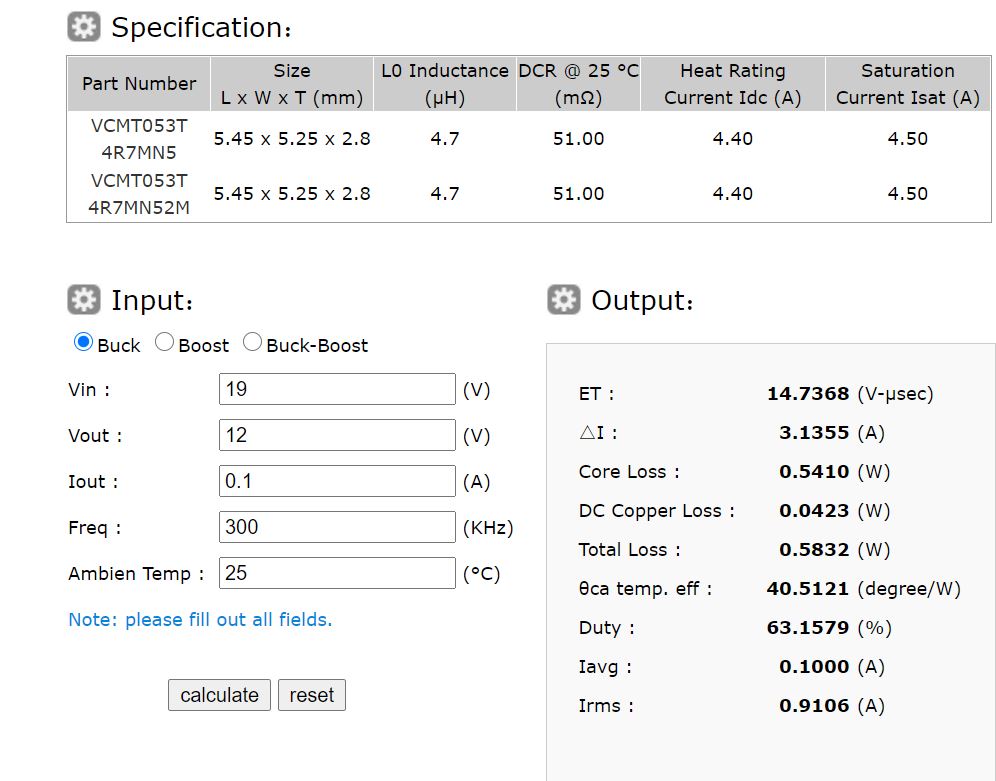
vin=19v
vout=12v (Ch2)
Iout=0.1A
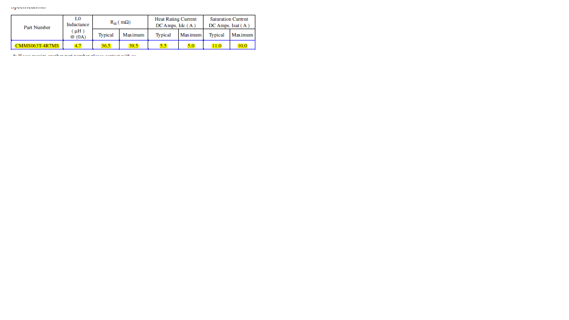
L=4.7u (DCR30m ohm)
When the output current is 0.1A and the inductor temperature is above 40C, MODE =CCM
Thank you