This thread has been locked.

If you have a related question, please click the "Ask a related question" button in the top right corner. The newly created question will be automatically linked to this question.

UCC27533: Only works the first time

Part Number: UCC27533

Hello,

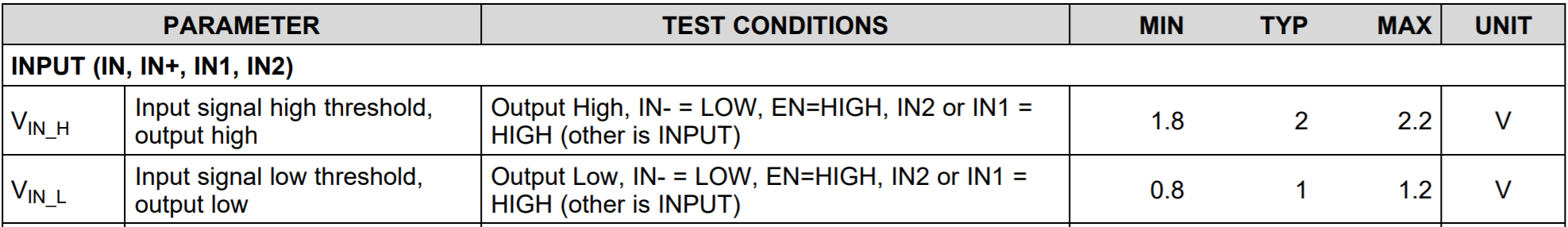
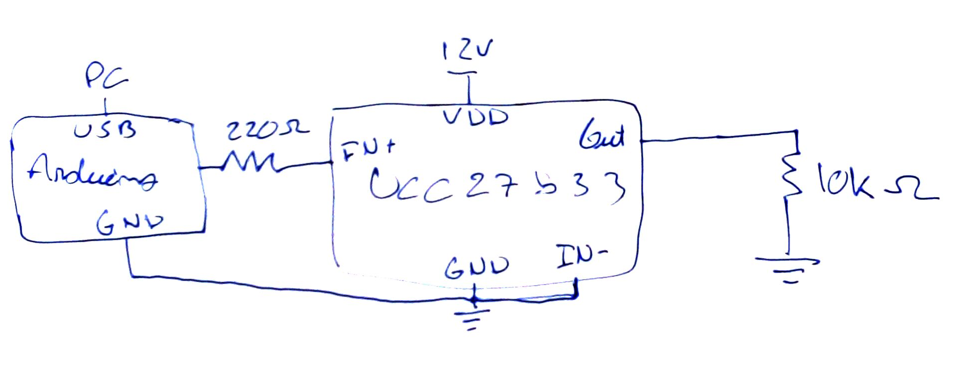
I am having a problem with this driver. I wanted to do a simple test so I soldered it on a perfboard and connected it to Arduino. I tried with 100nF and 1uF capacitors on the power supply but the results are always the same. I start by generating a PWM with Arduino, 5V 500 Hz 50%, it works fine. I change the duty cycle to 0%, it's ok; I change it to 100%, it's ok; When I change the duty cycle back again to 50%, it stops working. The signal on the output of Arduino is correct, 5V PWM duty cycle 50%. The signal on the input IN+ of the driver is attenuated, 1V PWM duty cycle 50%. The output of the driver is 0V. I try again the duty cycle with 100% but the driver never works again correctly. Eventually the signal on the input IN+ is always 0V, no matter what I do. I stop using the PWM of Arduino and connect the input IN+ directly to the VDD 12V. Nothing happens. When I remove the wire and connect it to 12V and after GND, 12 V again, etc, sometimes it start working. So on the output of the driver I obtain 12V as expected. But I have to do it many times.

I decided to use the IN- input, so the IN+ I connect to 12V. The result is the same.

I already tried 3 drivers, the result is always the same.

 Best regards

  • Manuel,

    Thanks for reaching out to E2E!

    Regarding your issue, I have a few questions / comments:

    1)  It makes sense that the 1V PWM at the IN+ pin would not make the driver switch, because of the input thresholds:

    2)  Can you please confirm that the value of the input resistor is 220 Ohm and not 220 kOhm?  Regardless, please consider replacing it with the recommended 150 Ohm resistor.

    3)  Regarding your supply bypass capacitors, are they placed physically close to the IC and across the VDD and GND pin?  Since they are Pin 1 and Pin 2 respectively, this should be reasonable to do.

    4)  Since you are using a perf board, do you have low impedance paths to all of your GNDs?  And how does your GND bounce look? 

    High dI/dt current from the driver output coupled with board layout parasitics can cause ground bounce. Because the device features just one GND pin which may be referenced to the power ground, this may interfere with the differential voltage between Input pins and GND and trigger an unintended change of output state. Because of the fast 17 ns propagation delay, this can ultimately result in high-frequency oscillations, which increases power dissipation and poses risk of damaging the device.

    I hope this helps and I look forward to hearing back from you.

    Thanks!

    Aaron Grgurich