


Other Parts Discussed in Thread: TPS65400
Hi,
I was planning to use the LP87561-Q1 IC for generating a 750mV VOUT as the supply for my DUT, and the max current draw is expected to be <2.5A (the buck regulator will be used in 4 phase mode). The buck IC will be on a separate board, which can be docked to the DUT board. I had the following doubts, could you please help me with the same:
- My total on-board cap for the DUT needing the supply from this buck IC is ~1.8mF (this is additional to the 22uF capacitors placed per phase at the buck output). I observed in the datasheet that the maximum tolerable output capacitance in order to meet the 1.9mV/us slew rate requirement in 4 phase operation mode is 2mF. So this should automatically imply that the buck can operate stably even with Cout_total loads as big as 2mF I guess? Since the part doesn't have a "COMP" input like say the TI TPS65400 IC in order to allow for external compensation adjustments, just wondering if we will still have comfortable phase and gain margin even with cap loads as high as 2mF or will we be right at the brink of instability? Is this buck specifically designed to be stable with such huge capacitor loads as 2mF with minimal compensation measures from the user?
- For my application, I was planning to make use of the remote sensing option, where I draw the sense FB_Bx lines from points very near to the DUT supply and GND pins, in differential manner. The concerns are:
- As I mentioned before, the buck IC will be on a separate board, which can be docked to the DUT board, so the sense traces can be up to 8 inches long or so, with the sense trace inductance being around 45nH, capacitance to the ground plane below the sense traces around 30pF and series resistance around 630mohm, for each single ended sense trace. Is the IC capable of operating stably with this sort of sense lines?
- Also, the big 1.5mF cap which constitutes most of the total 1.8mF cap is not exactly at the final point of load (POL) from where the sense lines are tapped, rather it is placed some 4 inches before that point due to the larger size of the capacitor. Can the IC remote sensing mechanism still work ok without instability concerns?
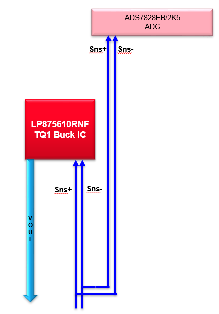
- Finally, in order to actually measure and record the sensed voltage for logging purposes, I was planning to branch out the sense lines also to an ADC (ADS7828EB/2K5) as shown below. Is this a cause for major concern for the stable operation of the buck?
Thanks,
Anoop

