This thread has been locked.

If you have a related question, please click the "Ask a related question" button in the top right corner. The newly created question will be automatically linked to this question.

BQ24630: Questions about charging time and constant current

Part Number: BQ24630
Other Parts Discussed in Thread: BQ25306

Hello TI experts,

my customer made PCB sample using BQ24630, there is some problems about charging time and constant current.

I show you some results below;

1. charging current is changed, (upper: 4A / below : 6A) termination current is same (300mA default)


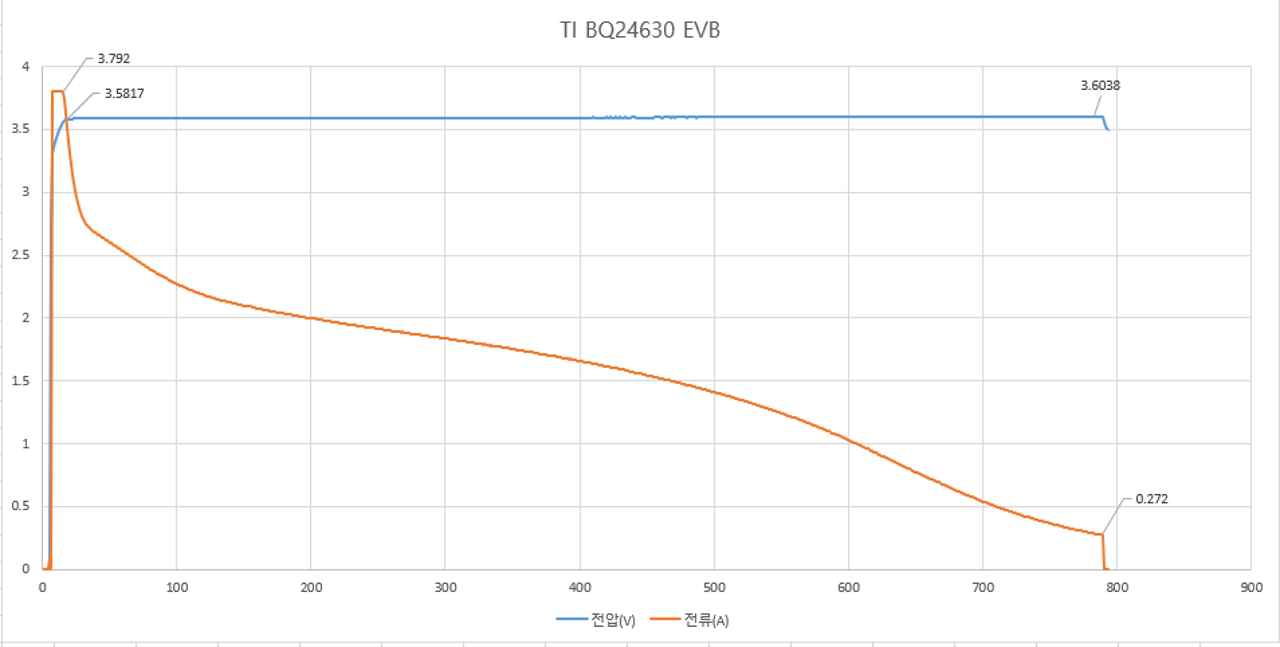
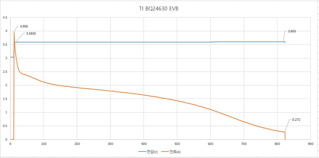
--- charging time is 13min (CC:4A), 14min(CC:6A)

2. termination current is changed (upper : 300mA / below : 1A), charging current is same (6A)

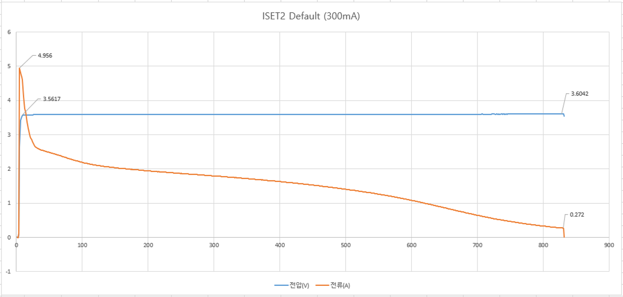
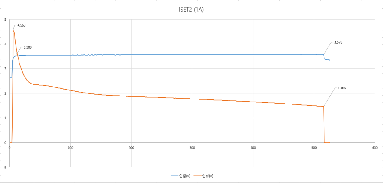
--- charging time is 14min(TC=300mA), 8m50sec(TC=1A)

Here is my question;

1. I can see the charging time is quite not different between 6A charging and 4A charging. even 6A charging is longer. is it normal operation?

2. I cannot see the constant current phase long time. even it ends less than 0.5 seconds, as you see the spike on orange voltage line. is it normal operation?

3. anyway our goal is to reduce the time. but i found only way to reduce the charging time, lower the termination current.

the result is as you see, time is quite reduced. but we cannot use the battery as long as we want. because final battery voltage is only 3.578V. (full voltage is 3.6V)

we can use the battery fully when the voltage is 3.6V compeletely.

4. is there any way to increase the time of constant current?

5. is there any way to reduce the whole charging time except lower termination current?

6. can i use the Li-ion charger for LiFePo4? if not, what is the side effect?

7. is there any solution for rapid charge of LiFePo4 battery?

and here is the information of our battery. (LiFePo4, 3.2V nominal, 3.6V max, 360mAh capacity)

Please check this issues. Thanks.

Best regards,

Chase

  • Hi Chase,

       Charge time is a function of your system and board layout as well. If you have impedance between the battery and where battery voltage is sensed, then this causes the charger to enter the CV loop earlier than expected (charger senses IR drop + real battery voltage), and causes a longer CV loop time. This is intended to make sure your true battery is actually getting charged fully and is expected behavior.

    Essentially you are charging at such a high rate for your small battery that you will not remain in CC for long. Due to the voltage drop across any wires or trace impedance, the real battery isn't actually at the fully charged voltage, so CV loop is active longer. This is desirable to fully charge your battery.

    There is no effect of using Li-ion charger as long as it can support your charge regulation voltage. BQ24630 is good because it also has a unique temperature profile geared towards LiFEPo4 chemistry.

  • Hi Kedar,

    I understand what you mean, anyway our purpose is to reduce charging time. end customer want about 7~8 minutes from empty to full.

    we can change anything including charger IC. could you recommend good solution for our situation?

    Best regards,

    Chase

  • Chase,

    It is possible that you may be hitting the I_DPM setting described in 8.3.4 Input Adapter Current Regulation. What is your I_DPM setting? Are you observing the adapter current clamped to the value I_DPM on the 4A and 6A boards?

    Best Regards,

    Ricardo

  • Hi Ricardo,

    I_DPM setting is default. from the equation, V_ACSET is 1.65V (100K-100K resistor divider from 3.3V V_REF) and R_AC is 0.01ohm

    so I_DPM is 1.65/(20*0.01)=8.25A.

    what will happen with this I_DPM in our PCB situation?

    and could you please explain if I_DPM is lower than present value? then I can suggest to test to my customer.

    Best regards,

    Chase

  • Hi Chase,

    IDPM should not be the issue here. As the setting is 8.25A you should not hit IDPM, and as you are observing your expected charge current which also tells us IDPM loop is most likely not active. If you are observing clamping of the input current then we can tell IDPM is active.

    The concepts I explained in the 1st post are related to battery and its chemistry, not the charger operation. All chargers will have atleast CC and CV phase. The issue is CV phase takes too long which is a function of the battery itself or layout/system (trace impedance, battery internal impedance, protector etc). The tradeoff to reduce charge time, is to not charge to full capacity.

  • Hi Kedar,

    Thank you for your reply.

    i understand that CC/CV phase time depends on the battery itself.

    then I have another question.

    1. can you suggest about circuit of battery PCM to reduce the time?

    in fact we don't know what components is important for reducing charging time.

    and it would be silly question, how about charging without PCM? can it be working and help to reduce the time?

    2. do you have any test data about charging time between LiFePO4 and Li-ion or Li-polymer with other same option?(same charging current and output)

    it will be very helpful with that data to determine next development.

    Best regards,

    Chase

  • Hi Chase,

       Battery pack pcm usually has back to back FET to prevent overdischarge or overcharge (Charge and discharge FETs). I would first focus on if there are long wires between battery pack and board, as this impedance will increase charge time by the largest factor. In layout focus on using short trace to reduce trace impedance. Then you can look at charging without PCM, however this does come with risks. One other option is to use the BQ25306 device with 3A current. This has a remote BATSNS pin that can be used to sense true battery voltage, and it also is standalone. Downside is it doesn't have the same TS charging algorithm.