Hi,
I was running load transient simulations for certain test cases based on the PSPICE transient model and circuit available at www.ti.com/.../snvmaz9. I used the SPICE models of the actual capacitors that I intent to use in my final application. In addition, I also added the actual SPICE models downloaded from theMurata website for the ferrite bead part "BLM21PG300SH1D" in the VIN_Bx and VANA input supply path which is the same part that's used in the TI EVM board for this part.
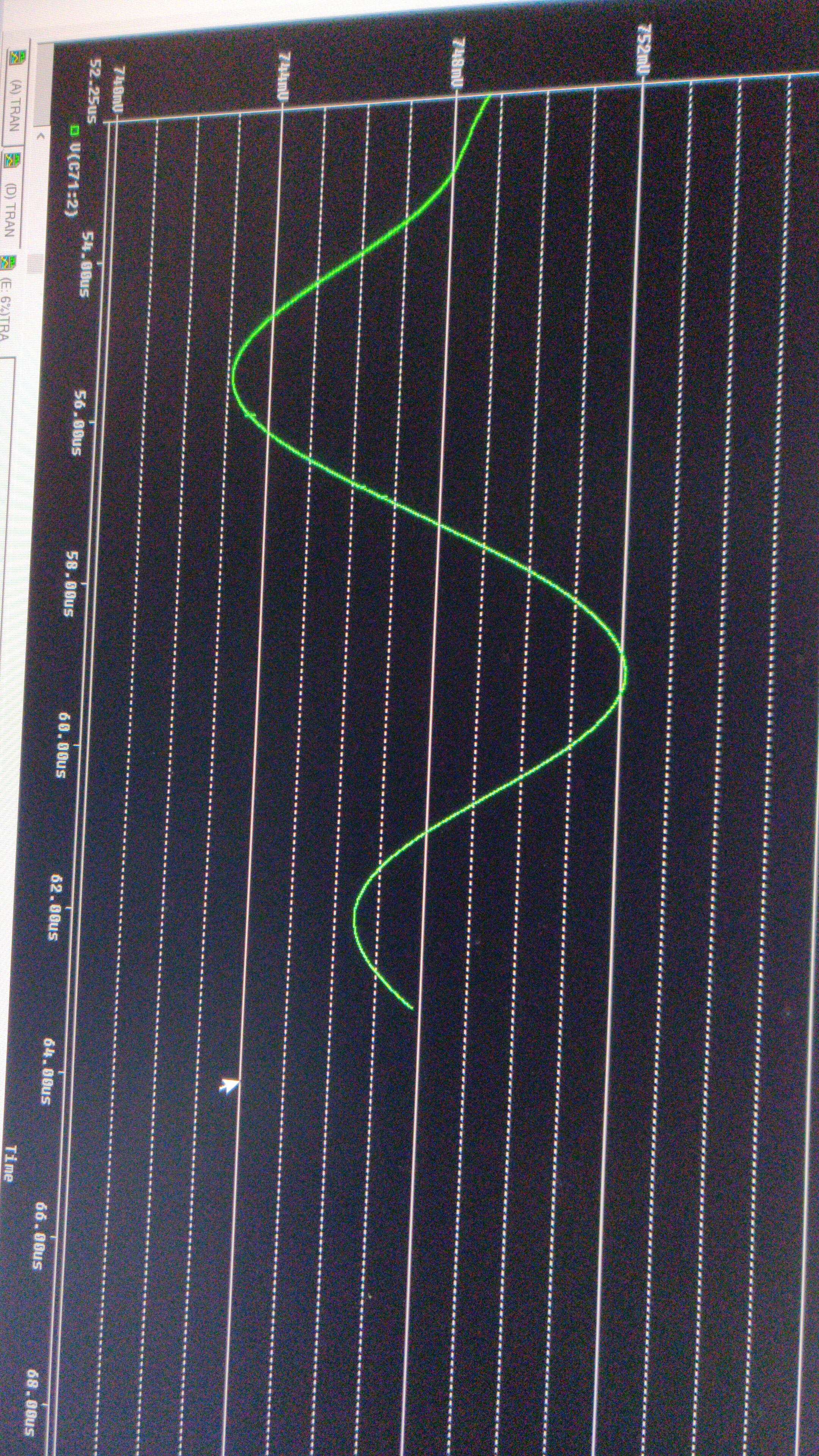
When these ferrite bead models are added, I see weird spikes in the VOUT waveform and later run into convergence issues in PSPICE transient sims. Waveform image below:

If I just short out these Ferrite beads, the waveform is clean and I don't see any convergence issues. Waveform image below:
My doubt is, is this a purely a simulation artifact due to the LdI/dt voltage ripple due to the Ferrite bead inductance when the buck draws in transient current from the input supply during the converter switching phases in conjunction with a perhaps not small enough max transient time step setting (currently it is 20ns, ie the same setting from the original PSPICE file that I downloaded), and in the real operational case these issues won't be visible? So I need not remove the Ferrite beads from the input supply path in my design?
Or is this a genuine concern even in the real life operation case and it is recommended NOT to use ferrite beads in the buck input supply path (even though I do see them in the EVM schematic)?
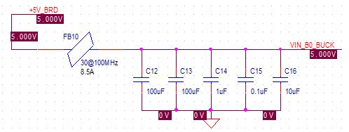
NOTE: My 5V input supply will be from either of the DC adaptors "MENB1060A0551F01" or "PPL36U-050" and I intend to have at least 500uF bulk bypass capacitors on the 5V supply (excluding the smaller decoupling caps):
Thanks,
Anoop