This thread has been locked.

If you have a related question, please click the "Ask a related question" button in the top right corner. The newly created question will be automatically linked to this question.

TPS40210: PMP4650 circuit

Part Number: TPS40210

Hello TI,

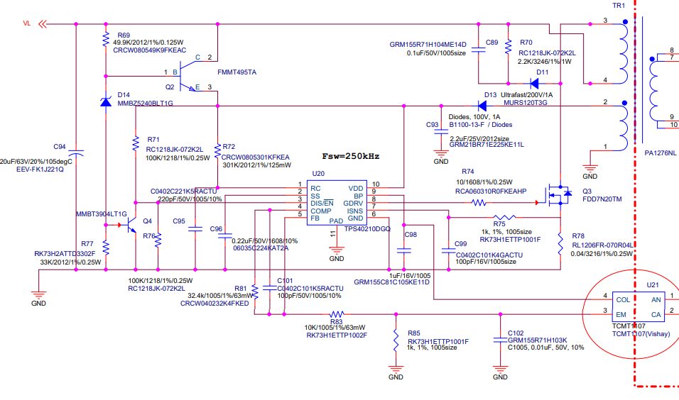
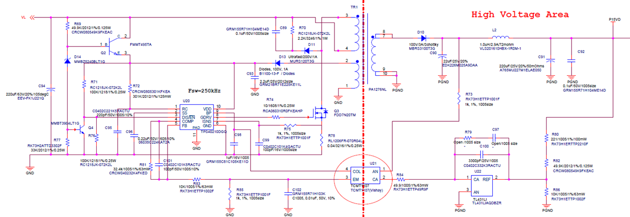
I designed a flyback SMPS based on the PMP4650.
However, the input voltage operates normally up to about 14V, but if the voltage (about 18V) is raised above that, the operation stops.
The cause of stopping the operation is that the dis/EN signal is high.
Element damage occurs between the base-emitter of Q4 and D14 is burned.
I changed the 33kohm of the R77 to 10kohm. The phenomenon is the same.
What could be the cause?

B. regards

SY

  • I add the circuit

  • Hello,

    Thank you for your message. The responsible person is not in the office today but she will answer to your question tomorrow. 

    Sorry for the inconvenience, 

    Elisabetta

  • Today I found a new fault.


    Q2 Collector-base failed with short.

    PMP-4650 reference design added diode to FMMT495TA base.

    Should I add it in the attached circuit?

    What is the purpose of the diode?

    Thanks 

  • Hello JSY,

    Yes, please add the diode in the base of Q2. 

  • Hello Brigitte,

    I added the diode and there is no problem.

    I don't understand why the diode is needed.

    Could you please let me know the reason why the diode is added?

    B. regards

    SY

  • Hello SY,

    The diode prevents backward current from happening, but I did not simulate the circuit yet to check when this can happen.

  • Thank you for your reply.


    I have an additional issue.

    As you know, I am using PMP4650 for 24V input system.
    I are planning to use it within the range of 18V to 30V.
    The output will be used around 15V 200mA.

    Questions:
    1) From Test, the start voltage is about 18V.

    Since it's zener 10V, I think we should move around 13V.

    I think it need to lower the 49.9 kohm. Is that right?

    2) Can you review the circuit as a whole?

    Thanks and B. regards

    SY

  • Hello SY,

    1) PMP4650 starts at around 13V. You mention your test shows 18V, is my understanding correct or do you want to start at 18V? 

    2) C89 is 10 times bigger than in PMP4650. Do you have a reason for it? 

    The 1 ohm resistor across the filter inductor on the output side is missing in our design.

    C23, D4 and R14 are missing in your design. This is a softstart circuit.

    R15 is missing and R13 is not coming from VOUT behind the inductor.

    BTW, which voltage do you have on the output? And in addition, the transformer is for sure not optimized for 24V, so possibly you are not getting the full output power.

  • Hello Brigitte,

    Thank you for your reply.

    1) I hope the start action is 16V.
    2) There is no particular reason. I will check it by modifying it to 0.01uF.

    The output voltage is 15V and the current is about 100mA to 150mA.
    I know that the Transformers are not optimised for 24V.

    Do you think this transformer has the problem to use?

    Why is the reson to use 1 ohm between filter inductor?

    Thanks and B. regards

    SY

  • Hello SY,

    1) Then you should increase the Zener to a 13V Zener instead of the 10V Zener.

    2) Ok.

    The transformer should be ok as long as you do not need highest performance.

    The 1 ohm resistor limits the impedance for high frequency, if it is necessary in your system would need to be tested, but I would at least place it in the layout.

  • Hello Brigitte,

    Is it right to connect the 13V zener?
    I think VDD voltage will increase around13V if we use 13V zener diode.
    Isn't it right to connect 49.9 kohm in parallel?

    Thanks and B. regards

    SY

  • Hello Brigitte,

    Thank you for your kind reply.

    Shouldn't we reduce 49.9 kohm? not 13V zener.

    Thanks and B. regards

    SY

  • Hello SY,

    I would change the Zener and keep the resistor.

  • Hello Brigitte,

    Ok, Thanks

    B. regards

    SY