This thread has been locked.

If you have a related question, please click the "Ask a related question" button in the top right corner. The newly created question will be automatically linked to this question.

TPS92682-Q1: Very high frequency gate oscillations killing MOSFETS

Part Number: TPS92682-Q1

I'm building a compact CC/CW led lamp with the TPS92682 as the driver.
Design specs are:

VIn = ~24V (6s lipo pack)    ;    VOut(max) = 55V (marginal, I know)    ;    IOut(max) = 2A    ;    POut(max) = 100W per ch
I have calculated the compensation network parameters after exporting the PDF: Chf = 3.3nF  ;  Ccomp = 10nF  ;  Rcomp = 680ohm.

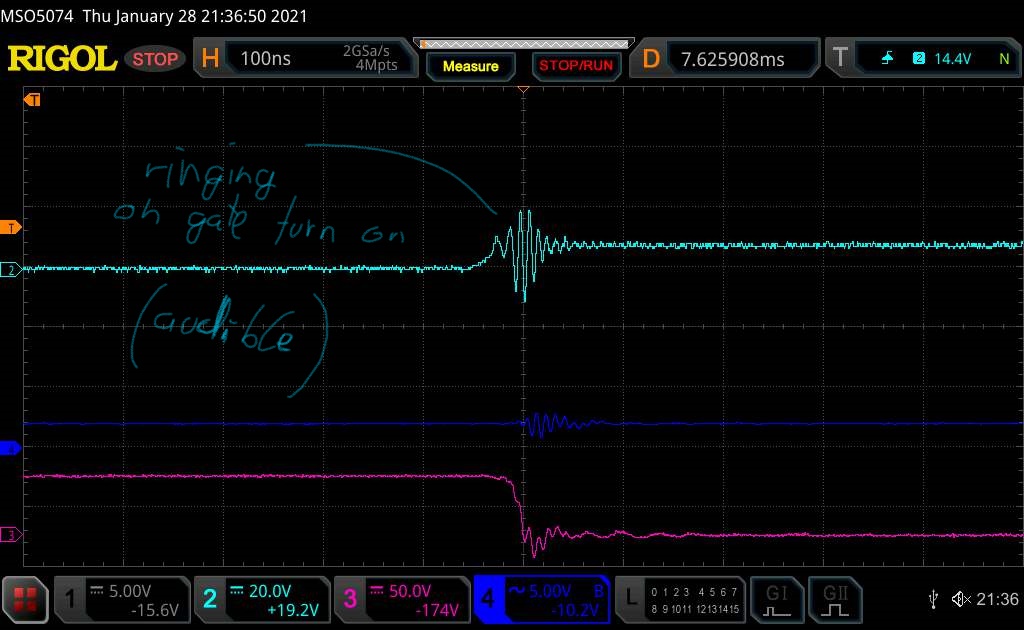
I am encountering a very weird behavior at higher output current settings (>20W), where the gate of the mosfet starts oscillating at >50MHz with 90Vpp (see attached images). 
The oscillations start appearing at gate turn on and off for ~3 cycles (above 15W output), but eventually become permanent, killing the mosfets in the process (in the pictures OVP kicked in and it saved the fet)

Has anybody encountered something like this before? 

Long time base view from startup to death

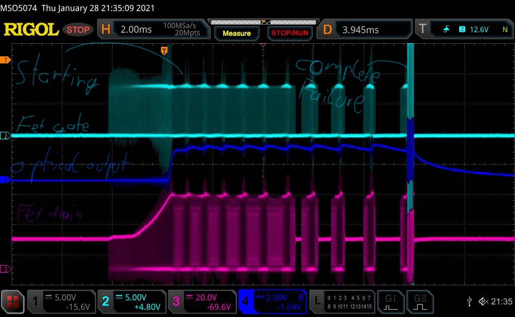
The problem starting 

Failure

Schematic and pcb CC-CW Lamp.pdf

  • Hi Thorben,

    Layout and component selection are of critical important in designing high power stages.  100W per channel with 85%-90% efficiency will have about 10W-15W dissipating on each the power stage for a total of 20-30W.  First the FET has to be of right voltage rating and can handle the power loss along with getting the heat out.  What is the voltage rating on the FET and mechanically is there away for the heat to dissipate out>

    The ringing you are seeing on the gate turn on can be due to the layout if the FET is far away from the TPS92682.  Note that there will always be small amount of ringing due to the trace inductance and FET input capacitance but the key is the voltage on the drain of the FET is behaving properly and not ringing.

    What is your switching Frequency you are designing to?  If it's not stable then you should start with Rcomp of 0 Ohm and Ccomp of 0.1uF to get the system stable first and re-compensate later after you have a chance to trouble shoot issues.

    Your schematic show electrolytic caps at the output and those can have high ESR and ESL.  I would recommend adding a 0.1uF and 10uF ceramic at the output to lower the impedance.

    Thanks Tuan

  • Thanks for getting back to me Tuan,

    Tuan Tran74 said:
    What is the voltage rating on the FET and mechanically is there away for the heat to dissipate out

    The traces to the mosfets are actually very short (the fets are right next to the chip) and routed directly over a ground plane, so their inductance will be decently low. 
    The fets are 100V TO220 devices, that are screwed directly to a heatsink block that will deal with the heat easily.

    Tuan Tran74 said:
    Your schematic show electrolytic caps at the output and those can have high ESR and ESL.  I would recommend adding a 0.1uF and 10uF ceramic at the output to lower the impedance.

    Will do that :)

    The switching frequency should be around 100-200kHz (not sure how the large-ish mosfets will deal with anything higher), and I have already attempted over compensating the circuit with no luck.

    The oscillation issue is particularly strange, since the oscillations that kill the mosfets (as seen in the last image in the original post) aren't just some overshoot from trace inductance, but instead an actual driven oscillation that seems to increases in amplitude (at many mega-herz). The death of the transistors is also very sudden (probably from shock heating from being driven at such high frequencies), even if they stay <10°C over ambient in normal operation.

  • Hi Thorben,

    VCC and VDD should have 2.2uF to 4.7uF ceramic on the pin and you only have 1nF.  Please change that and re-test to see if the problem still exist.  I would start with 100KHz switching frequency and lower commanded output current for the LED and slowly ramp up the current see if you can debug a little better as to where the problem truly is. 

    What is the part number of the FET and diode?  What is the saturation current of the inductor?

    Thanks Tuan