This thread has been locked.

If you have a related question, please click the "Ask a related question" button in the top right corner. The newly created question will be automatically linked to this question.

UCC21750-Q1: Three- Phase Inverter Design

Part Number: UCC21750-Q1
Other Parts Discussed in Thread: UCC21750, , TMS320F28069M

Hi team,


Good day.


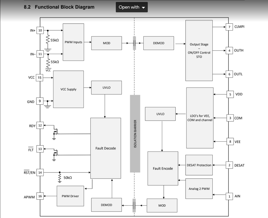
Our customer is designing a three-phase inverter using UCC21750-Q1 and they are using six of these. The application information in the datasheet of UCC21750 gives an example implementation. It uses a pull-up resistor for each of nFLT, RDY and nRST pins. What is the proper connection of these pins for six UCC21750-Q1 gate drivers?


This particular post (https://e2e.ti.com/support/power-management/f/196/t/919218  uses an ANDing scheme to connect the nFLT pins. Is this a necessity? Our customer thought of implementing this was connecting these pins altogether using a single pull-up resistor, however, they need to connect these pins to the GPIO of the TMS320F28069M. What would be the suggested connection to check if this could be paired with the TMS320F28069M's GPIO pins?


Thank you for the assistance.


Regards,
Carlo

  • Hi Carlo,

    Welcome to E2E!

    The for the nFLT, RDY, and nRST pins for six driver could be all shorted together with only one pull up resistor. What each pin of each gate drivers does need is a local by-pass capacitor near each pin of the gate driver. This local capacitor (100pF capacitor in the datasheet) will help the noise immunity of each of those pins to prevent abnormal behavior of the gate driver.

    As for the post you linked, you don't need to have an AND gate IC. The nFLT pins can all be shorted together and feed straight into a micro controller. 

    Let me know if there's any additional questions!

    Best regards,

    Andy Robles

  • Hi Andy


    Thank you for your response. Our customer has further questions as follows:

    1. I am satisfied with nFLT & RDY as there are open-drain FETs internal to the UCC217xx series & 5k pull-ups would do the job along with local bypass capacitors.

    2.However, the nRST/EN has a 50k pull down resistor internal to the IC and hence adding a pull-up would be:

    a. Redundant: Since the pull-down and pull-down will be in contention and always lead to some sort of current flow.

    b. From the controls point of view, I feel that it would be better to first wait for the RDY & nFLT pins to be high and only then assert a high signal on the nRST/EN to start all the six devices. And, after some delay, allow the application of the PWM on the inputs of the Gate Drivers.

    Thus, the Board Support Package would have an initialization code that sets the nRST/EN to low. And, then wait for nFLT & RDY, and then execute nRST/EN = 1. What would be your opinion on the same?


    Regards,
    Carlo

  • Hi Carlo,

    I understand and agree with the customers comment. A pull resistor on RST is not necessary and from a control stand point it does make sense to do what they mentioned:

    "first wait for the RDY & nFLT pins to be high and only then assert a high signal on the nRST/EN to start all the six devices. And, after some delay, allow the application of the PWM on the inputs of the Gate Drivers"

    I have no concerns with not using an pull up resistor on RST, and applying a high voltage on RST just as they described.

    Best regards,

    Andy Robles