This thread has been locked.

If you have a related question, please click the "Ask a related question" button in the top right corner. The newly created question will be automatically linked to this question.

TPS2359: Configuration of TPS2359 gets reset

Part Number: TPS2359

Dear,

I'm trying to power on the A side of the TPS2359 with writing 00101111 to register 1. Sometimes (ie. not on every occasion of doing this) the readback values of the TPS2359 are reset to the factory values ; exactly the same as in PDF, except for the register 9. All the settings fro mother registers, like regisiter 0 and alike, for both parts A and B are at the default values. The 3.3V and 12 Vpower rails seem to be down as the target is not powered on. I'm only using A side of the TPS2359, ie. the side B in not being powered on at all.

What is going on here? Any hints on how to debug and investigate this issue?

Thank you in advance!

  • Hi Hinko,

    When you see the registers of the device being reset to default values, have you probed the VINT rail ? Is there any glitch on the VINT rail ?

    Did you capture any waveforms during the instant when the registers get reset to default ?

  • Dear Praveen,

    I need yet to perform those measurements you mention. I will to check the VINT. Thanks for the tip on where to start looking.

    Which waveforms would like to see captured? I2C communication?

    Thanks!

    Hinko

  • Hi Hinko,

    I was referring to various analog signals (Vin, PASSA, BLKA, VINT, OUT12A ) waveform captures during startup and the instant at which the registers reset to default.  

  • Got it.

    I try to get readouts of those signals now that you seem to be suggesting this to be power supply related. I'm thinking on using drop on the VINT to trigger the acquisition of others.

    Cheers,

    Hinko

  • Dear Praveen,

    Here are some of the findings regarding the voltage levels.

    IN12A is stable at 12.4 V, no glitches observed at any time.

    IN3A, Vdd3A stable at 3.63 V, no glitches observed at any time.

    VINT is at 2.38V at all times; when load is power on, powered off and while at the failed power on instant.

    SUM3A is at 146mV when load is powered off, 207 mV when load is on and 55 mV after fault (IC registers at factory defaults).

    OUT3A is at 3.63V when enabled, 0V when disabled. In case of faulty start it goes to 1.62V.

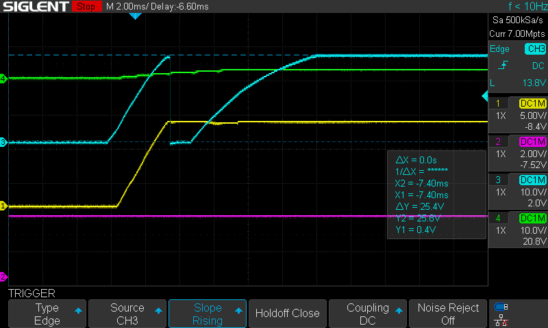
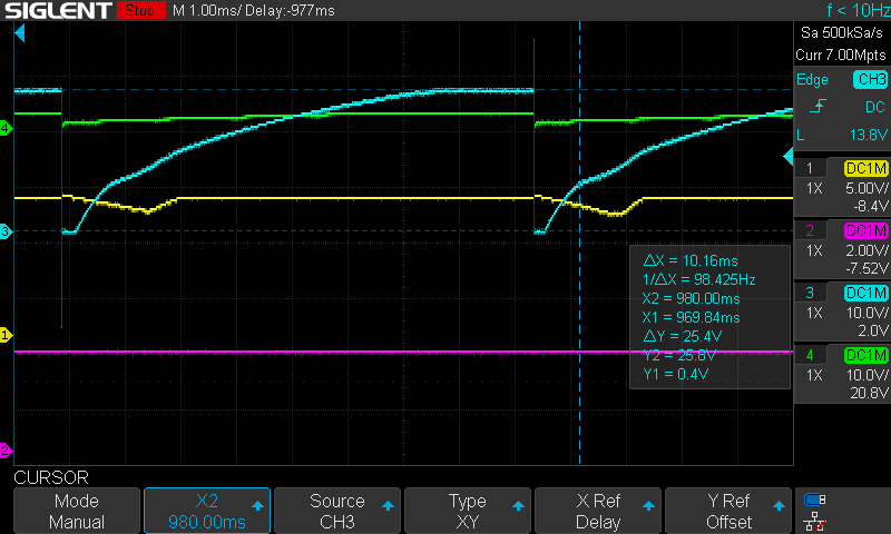
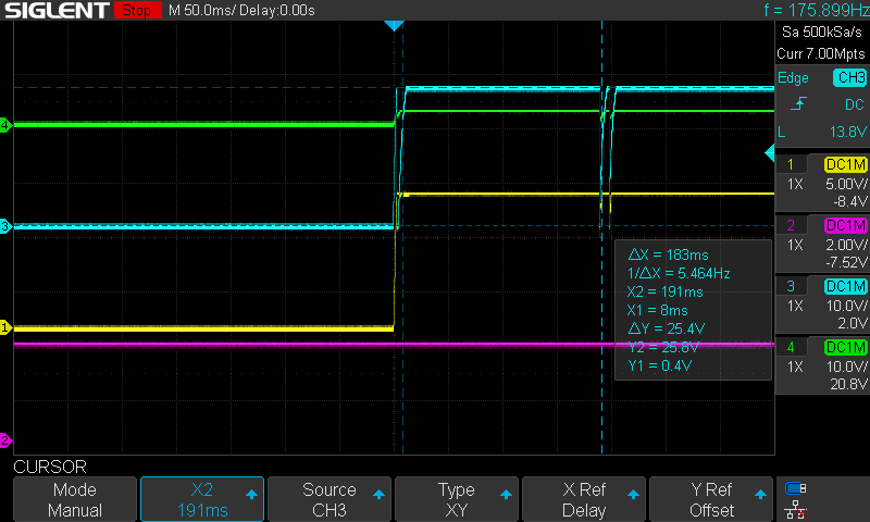
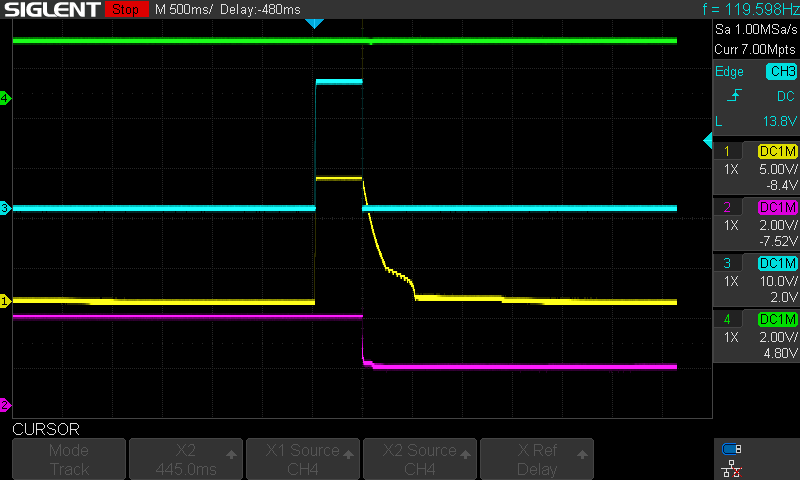
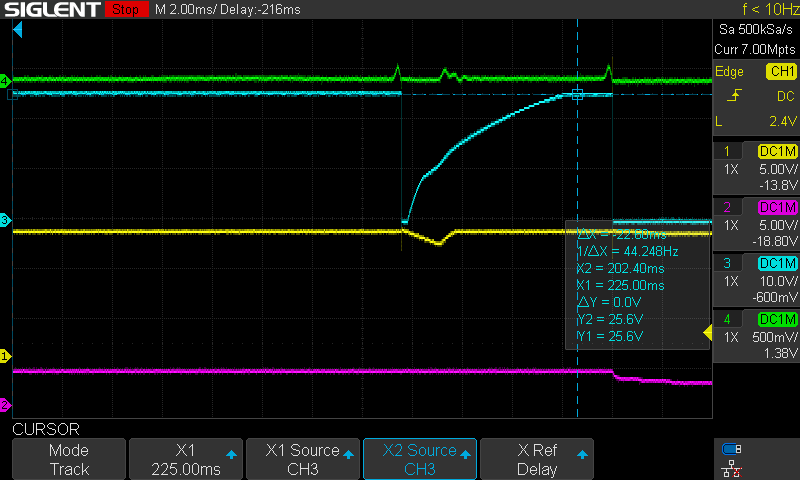
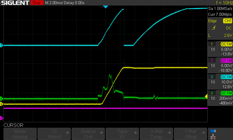
    In the image below traces are as follows Yellow: OUT12A, Pink: OUT3A, Blue: BLKA, Green: PASSA.

    Image1: This a normal startup; load was successfully powered. This is right at the moment of sending the power on command.

    Image2: This a normal startup. This is observed in the successful startup, about ~900ms in. I've seen these type of transitions every time after power up. The offset time when actually happen differs but the load still powers nevertheless.

    Image 3: Another example of the successful start up with transitions seen at a different delta T offset.

    I did observe the reg8 to be 0x03 in all successful power on cases. The reg8 goes to 0x00 after read again for the second time.

    Image 4: The failed start up looks like this (heavily zoomed out). On zooming in to the startup the waveforms are the same as in successful startup. The transitions were not observed before the failure to start occurred (OUT12A going to 0V and OUT3A going to 1.62V). The time that OUT12A is present is about 180 ms.

    Image 5: In this image the Green is SUM12A. The startup failed.

    Image 6:  A zoom in into the startup with SUM12A (green). In this case the startup was successful, but I would expect that it would be the same as for failed start given from what I've seen.

    As far as I can tell, the 12SUMA does not look like seen in TPS2359 datasheet.

    I can do more measurements if required.

    I would also like to mention that if the 12AHP=1 I do not see the power up failures (I've been trying to see the failure for coupe of hours and have not seen it, while with 12AHP=0 it takes minutes to observe the failed start up).

    Another thing I noticed is that after a successful startup the reg8 is always 0x03. Not sure if this is something to be worried about since the startup does not fail.

    Thank you!

    //hinko

  • Hi Hinko,

    Thanks for sharing the waveforms. We are looking into these and will come back to you by tomorrow, 10/Feb/2021.

    Best Regards,

    Avishek

  • Hi Hinko,

    Please could you help us to understand the issue better by providing the below information:

    1) Kindly confirm that the probe setting is at 10x.

    2) Capture the 12V rail current waveform to verify why BLKA is coming to zero and then going up.

    3) Please share the schematic and resistor settings on pins SETA, SUM12A, and SUM3A.