This thread has been locked.

If you have a related question, please click the "Ask a related question" button in the top right corner. The newly created question will be automatically linked to this question.

LM2831: Noisy output at low temperature

Part Number: LM2831

Hi Team,

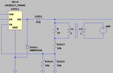
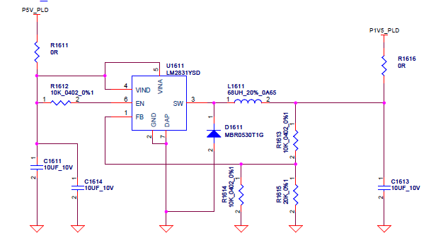
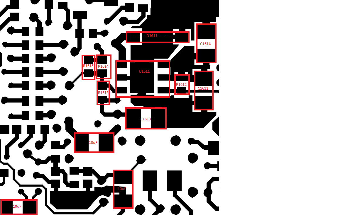
We have a customer using LM2831YSD/NOPB for a 5VDC to 1.5VDC converter with a maximum output current of 80mA. Under certain conditions (mostly low temperatures) the output voltage is very noisy. He has simulated the design using the SPICE model but it seems that the LM2831 is unstable. The inductor, B82462G4683M000, is on the other side of LM2831. Can you please help us trace the possible cause of the noise?

Regards,

Danilo

  • Hi Danilo,

    Thank you for your question.

    There are a couple of points that I would like to discuss with you:

    1. I think you should check the closed loop stability of your system. I see that your inductor has an inductance (68 uH) that is much larger than the values used in the several design examples present in the datasheet (that are in the range of a few uH). Thus I would advise you to revise the inductor value and/or to verify the phase margin of the system (it could be that a low phase margin brings you unstability at low temperature).
    2. The layout could be improved, starting from bringing the inductor on the same side of the IC and minimizing the parasitic among input capacitors, inductors, diode and output capacitors. I leave you as reference the following application notes: Five steps to a great PCB layout for a step-down converter (ti.com)

    Please ask again if you have any more questions.

    Thanks,

    Stefano 

    All information in this correspondence and in any related correspondence is provided “as is” and “with all faults”, and is subject to TI’s Important Notice (http://www.ti.com/corp/docs/legal/important-notice.shtml).

  • Hi,

    Thank you very much for your help.

    Stability check:
    Yes I was thinking of doing a closed loop stability check.
    In order to do this i intend to:
    - Add a small (10-20 ohms) in series to feedback loop resistor
    - Inject a sin wave through an injection transformer on this resistor.
    - Compare Vin (injection) & Vout (output voltage) depending of injection frequency.
    See Gain_Phase_Margin_drw for a drawing of what I intend to do.

    Would this seem the best way to do this?


    Inductor value:
    The datasheet is not very specific about this. Should I consider transient currents for Iout max (capacitor in rush currents)? I am trying to understand what was missed and how TI calculates a 10uH inductor even when my max steady state current is 0.08A.
    Vin = 5V
    Vout = 1.5V
    Imax = 0.08
    ΔIl = 0.2*Imax = 0.016
    Ts = [1.4; 2.5]us
    L = [47;82]uH

    Thanks again!

    Kind regards,

    Benjamin Derouineau

  • Hi Benjamin,
    Thank you for your questions.

    According to the loop stability measurement, your procedure should be fine.
    Just in case you had any doubt during the operation, you can refer to: How to Measure the Loop Transfer Function of Power Supplies (Rev. A)

    According to the inductor value, your calculations are correct. The fact is that your output current is much lower than the nominal one (lower currents intrinsically leads to higher inductance values).
    The close loop measurements should tell you if this could be a problem or not.

    In the worst case, you could decide to reduce the inductor values (this would increase current ripple and modify the expected efficiency) to
    improve stability.


    For a quick reference tailored to your application, please check our WEBENCH® POWER DESIGNER .


    Please ask again if you have any more questions.

    Thank you,

    Stefano

    All information in this correspondence and in any related correspondence is provided “as is” and “with all faults”, and is subject to TI’s Important Notice (http://www.ti.com/corp/docs/legal/important-notice.shtml).