This thread has been locked.

If you have a related question, please click the "Ask a related question" button in the top right corner. The newly created question will be automatically linked to this question.

TPS65261: Regarding PGOOD and RESET

Part Number: TPS65261

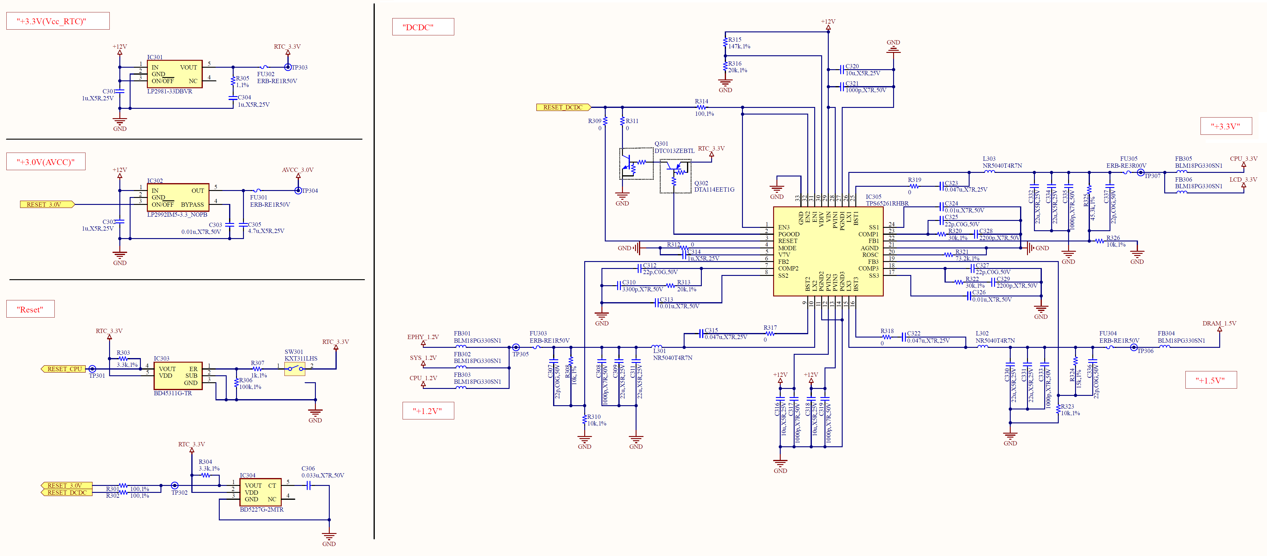
In the attached circuit.
R309 and R311 are not mounted.
=> Signal "RESET_DCDC":H , TPS65261-2(PGOOD):H
R309 and R311 are mounted
=> Signal "RESET_DCDC":L , TPS65261-2(PGOOD):L

With R309 and R311 mounted, what should I change to make "PGOOD(pin2):H" and "RESET(pin3):H"?

  • Hi, Sir 

    Why do you connect Q301's collector to EN1/2/3? 

    After Vin power on, initial PGOOD will pull low EN1/2/3, then Buck1/2/3 output will never rise up, then PGOOD will always keep low, the IC will always in lockout. 

    So we cannot mount R311, cannot use PGOOD to control EN1/2/3 signal. 

  • I had connected the collector of Q301 to EN1/2/3 because I thought the default value of PGOOD was H.

    In addition
    R311 is not mounted, R309 is not mounted
    => 3.3V, 1.5V, 1.2V output respectively (EN1/EN2/EN3=H)
    R311 is not mounted, R309 is mounted
    => 3.3V, 1.5V and 1.2V are 0V (EN1/EN2/EN3=L)

    I would like to know the part to be modified.

    Best regards.

  • Hi Sir,

    Zhao will feedback to you after the Chinese new year holiday. Thanks.

  • Hi, Sir 

    The connection of RESET pin is not correct too. 

    See the Figure22 of datasheet, it gives a example for RESET pin, we just need to pullup to V7V or external 3.3V by a 10-100kohm resistor. 

    Note: 

    The PGOOD and RESET are the indictor signal which are usually used to enable/disable other ICs, not itself.  

  • Thank you for your answer.

    Can you tell me if there is a sample circuit that uses the RESET pin to turn off EN1/EN2/EN3 when there is a problem with the TPS65261?

    In this circuit, "RESET_DCDC" is pulled up by 3.3V.
    When normal, "RESET_DCDC" = "H" / "RESET" is "H
    When abnormal, "RESET_DCDC" = "L" / "RESET" is "L
    I thought it was going to be "H", but it didn't work as expected.
    (I think this usage is using other IC only for enable/disable, but am I wrong?

    Best regards.

  • Hi, Sir 

    "R311 is not mounted, R309 is mounted
    => 3.3V, 1.5V and 1.2V are 0V (EN1/EN2/EN3=L)"

    Actually, I also think this result is strange. 

    Could you measure the VDIV pin voltage? is it higher than the 1.23V threshold? 

    If yes, the RESET should be high, the EN1/2/3 will be high too, then 3 Bucks should start to work normally. 

  • I'm sorry for the late reply.

    The measurement results are as follows.
    R311: not mounted. R309 not mounted. => VDIV=1.49V , EN1/EN2/EN3=H
    R311: not mounted, R309 mounted. => VDIV=1.41V , EN1/EN2/EN3=L

    If you make the circuit not to control other IC by RESET signal, it will work properly.
    However, I want to use the RESET signal if possible, so I need your advice.

    Best regards.

  • Hi, Sir 

    "R311: not mounted, R309 mounted. => VDIV=1.41V , EN1/EN2/EN3=L" 

    VDIV=1.41V > 1.23V, the RESET should be high. 

    From your test results, it looks the RESET is low, It is weird, we should look into this. 

    Some questions: 

    RTC_3.3V is low or high when "R311 not mounted, R309 mounted." ? 

  • "RTC_3.3V" is 3.3V in both cases.

     Measurement point of each channel.
      1ch:12V
      2ch:RTC_3.3V
      3ch:EN/EN2/EN3
      4ch:VDIV


    Case 1. "R311=NM_R309=Mount".

    Case 2. "R311=NM_R309=NM"

    From this, I am wondering why RESET is in the On state even though VDIV = greater than 1.26V.
    The pattern is also attached around RESET for reference.

    Best regards.

  • Hi, Sir 

    We check this on EVM and duplicate this issue. 

    Confirm with designer, the RESET logic is related with V7V, and V7V is related with EN1/2/3, V7V only rises up when one of EN1/2/3 is high. 

    In other words, one of EN1/2/3 must be high first, then V7V rises up, then RESET logic will be normal. 

    So for your case, RESET cannot be connected to EN1/2/3.