This thread has been locked.

If you have a related question, please click the "Ask a related question" button in the top right corner. The newly created question will be automatically linked to this question.

BQ2970: LiPo battery is drained down to 0V

Part Number: BQ2970
Other Parts Discussed in Thread: BQ51050B,

Hi everyone,

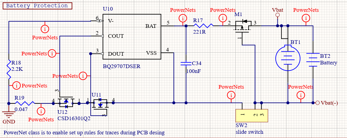
I designed a PCB that operates with a LiPo battery and charge with wireless charging (bq51050b) . At the very beginning of the circuit I have placed the bq29707 battery protector 

https://www.ti.com/lit/ds/symlink/bq2970.pdf?ts=1613323147424&ref_url=https%253A%252F%252Fwww.google.com%252F

According to the datasheet the undervoltage protection level for bq29707 model is 2.8V.

This is the sub-circuit with the battery protector. BT2 is the LiPo battery. Please ignore BT1 (this is for a coin cell battery option)

The circuit works normally and the cutoff level works as expected.. When I finished with the initial test I left the prototype laying around for around a month with the battery connected to it (this is going to be a device with integrated non-removable battery). After this period I decided to make some additional tests and I realized that the battery was drained down to 0V. As a consequence, the wireless charging cannot charge the battery and I have to replace it. I know that batteries have some self-discharge but I am sure that is not the reason behind then drain to the button effect.

Any suggestions? I need to maintain the battery level at least to 2.8V

Thanks in advance
Nick

  • Hi Nick,

    I don't know why your battery went to 0 V.  If you can  reproduce the condition check current draw.  When the part goes to the undervoltage state at 2.8V, the V- pin should pull up to the BAT voltage and the current for the part become very low.  You might check if V-  (GND) is not pulling up leaving the part on in a higher current state.  Also look for any leakage paths not shown in the circuit above. 

    A requirement to maintain 2.8V may be difficult with the BQ2970, the highest UV level available from the part family is 2.8V.  Although current from the load should cut off at this voltage and the cell voltage will normally recover some when that happens, the shutdown current does still exist and you have no margin between the 2.8V cutoff and the 2.8V minimum.  

  • Thank you for you response WM5295,

    I will measure the current drawn after cut-off and confirm if the V-  pulling up to BAT voltage.

    I will return with feedback ASAP

    WM5295 said:

    A requirement to maintain 2.8V may be difficult with the BQ2970, the highest UV level available from the part family is 2.8V.  Although current from the load should cut off at this voltage and the cell voltage will normally recover some when that happens, the shutdown current does still exist and you have no margin between the 2.8V cutoff and the 2.8V minimum.  

    But this is the case with all battery protectors, isn't it? I mean, all the battery protectors have some shutdown current that will gradually reduce the battery's voltage (if there is a long period of inactivity). Is there any advantage if I select a battery protector with lower UVP (let's say 2.5V)? I mean in the terms of the margin that you're referring to.

    Nick

  • Hi Nick,

    Yes, it is a challenge in a system if the user completely discharges the cell and leaves it set for long periods.   Ideally your cell/system might have a 2V minimum with the protector cutting off at 2.8V so that you would have 0.8V of margin for the cell & electronics to self discharge. But in many systems it is desired to get the maximum capacity out of the cell leaving little or no margin on the voltage and trusting the user to charge the cell/system when depleted.   Still when the part cuts off if V- pulls up the current should be very low.  Hope you can find the current drain.

  • Thank you for your responce,

    Please keep this ticket open and I will return with feedback.

    Nick

  • Hi WM5295,

    I performed some measurements using a bench power supply for the tests. First of all when the voltage goes below 2.8V the battery protector (BP) interrupts the load as expected. Then I measured the V- with reference to Vss for two different BAT voltages:

    BAT = 2.7V -> Vss = 1.54V (ΔV = 2.7 - 1.54 = 1.16V)

    BAT = 2.0V -> Vss = 0.88V (ΔV = 2.0 - 0.88 = 1.12V)

    I was expected the V- to be the same as BAT.. Any comments? What may cause this voltage drop?


    Also I was monitoring the current drain, for BAT=2.7V the current was going from 0 to 1.5uA and then back to 0 (and this cycle was repeated). I suppose that this is the self consumption of the battery protector? Why it goes to 1.5uA and then back to 0? When I was reducing the voltage down to 2V i wasn't able to measure any current drain..

    Nick

  • Hi Nick,

    When you measure, are you measuring PACK- or V- with respect to VSS?  If yes, you are pulling down on the V- and the meter is looking like a weak charger.  The part will be trying to decide whether to recover.  Normally a load on PACK terminals pulls V- to BAT+.   The part pulls up with the 300k, but if the V- voltage is high enough I believe this turns off to reduce current. The pulsing is common as I recall if a meter, scope probe or weak charger is pulling down V- (forcing a pack voltage).

    Even if the 1.5 uA was steady, it casually does not seem like that would completely discharge the cell, but that depends on the cell.  Have you identified other currents which may be the issue?