This thread has been locked.

If you have a related question, please click the "Ask a related question" button in the top right corner. The newly created question will be automatically linked to this question.

TPS57040-Q1: Is it feasible to use external error amplifier?

Part Number: TPS57040-Q1
Other Parts Discussed in Thread: LMR33610

Dear team,

My customer plans to design a discrete battery charger solution for 12V battery with our TPS57040-Q1 device.

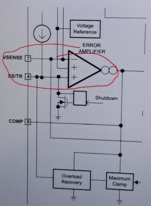
He hopes to use external error amplifier instead of the internal error amplifier, and the output of the external error amplifier connects to TPS57040-Q1's COMP pin directly. Is this feasible?

In addition, the input is 14.5V and the output voltage is 13.8V. I use the webench to simulate, and it works. But I didn't see what is the max duty cycle in the datasheet. So I still want to confirm what is the max duty cycle of our device?

Thanks & Best Regards,

Sherry

  • Hi Sherry:

    cause the COMP voltage also impact the eco mode, so the external comp votlage may miss trig this mode, so we suggest customer do a full test if they want to use this way,

    for max duty, it is not fixed value, in datasheet section 7.3.4 , it has detailed description. In summary , it will work as large duty as it can until the boot voltage drop to UVLO condition. when it trig boot UVLO, the output ripple voltage may become large.

    Thanks

  • Hi Daniel,

    Thanks for your reply!

    Could you please tell me how to control the voltage between BOOT and PH >2.1V?

    Thanks & Best Regards,

    Sherry

  • HI Sherry:

    it can't be controlled, when you want to reach 100% duty, the boot will discharge because the diode does not conduct. so if you want to keep Boot to PH>2.1 with 100% duty, you need force to add a 3.3V or 5V voltage between Boot and PH. 

    if customer want to have a good dropout performance, new generation like LMR33610 can be choose . CC/CV circuit can been added externally by controlling the FB node.

    Thanks